One of the best tidbits of advice I received was to use a GerberViewer
I agree - but I don't see a Gerber file here, only a screenshot.
I don't know if some of you have read the "SMPS PCB" thread, but I am working on an SMPS kit complete with toroid and heatsink and all the protection circuits onboard. You get a choice of a full heatsink with room for your amplifier - or just a 4" wide 'slice' that contains the power supply. The heatsinks are exactly the same as the old PPI ProMos series, but in black anodized - might do black powdercoat, but it's not as heat efficient. Any takers?
Output Rectifiers
Richie00boy and Jack,
Try looking at Onsemi's MUR1620CT and MUR1620CTR. These two diode pairs are both 16A (8A per leg) with a 200PIV ratings. The 'CT is common-anode, while the 'CTR is common-cathode.
The 'CTR forms the negative halh of the full-wave bridge, however, that type of diode pair is not used here. THe 'CT & 'CTR are used in commercial car amplifier SMPSs.
Steve
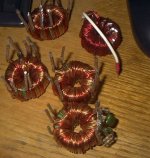
Hi N-Channel I got a bunch of these on the cheap from a friend who got them from where ever. They are 59*002701 fair- rites or equivlents. They are wrapped with what looks to be 18 guage wire with 7 primary wires and 4 secondary wires and they are 1:2 ratio transformers. The are 2 seperate primaries with 4 wraps each which makes there frequency somwhere between 30 and 40k they seem to work very at 32k.
I do not plan on sending out for boards I don't need silkscreening or anything fancy, I can do the rest here.
HI PowerCrest Labs I have tried looking at your link before and I don't know why but I just get a hosted by tripod in the corner and no picture?
I do not plan on sending out for boards I don't need silkscreening or anything fancy, I can do the rest here.
HI PowerCrest Labs I have tried looking at your link before and I don't know why but I just get a hosted by tripod in the corner and no picture?
Attachments
EASYAMP, thanks for responding, sorry your having trouble with the link. I got the same message as you. If you highlight the text below, and copy and paste it into your address bar, I guarantee you it will work.
http://valveaudio.tripod.com/images/schematics/switcher1.JPG
JUSTIN
http://valveaudio.tripod.com/images/schematics/switcher1.JPG
JUSTIN
Hi PowerCrest,
The supplies are somewhat similar.
My output voltage with 13.0v in is 38Vdc+/-.
I returned my primary snubbers to V+ instead of ground which when done correctly can do almost as good a job with smaller discharge resistors.
The other design uses feedback, mine is unregulated.
Does the sg3524 have the same shoot through circuitry as the sg3525?
If you are working on boards that you are going to offer, I would suggest putting in the soft-start circuitry, regulating the output, and a really good dose of EMI filtering on both inputs and outputs.
the primary reason for regulating the output is the wide fluctuation in input voltage in the auto application --
i just sketched this out for an application with a wide range of input variability, and current demand from 1.5 to 4 amps with a switch operating at 40kHz -- this will cover the range for a lot of amplifiers:
Attachments
Diode symbols
Rich-
Those are Schottky diodes. The difference between them and the Zener symbol is that theanode line is wavy, while the Zener's anode line is jagged.
Schottkys have lower forward voltage drop. Problem is, that currewntly, there is no negative pair for the Schottkys, only positive pairs.
Steve
Rich-
Those are Schottky diodes. The difference between them and the Zener symbol is that theanode line is wavy, while the Zener's anode line is jagged.
Schottkys have lower forward voltage drop. Problem is, that currewntly, there is no negative pair for the Schottkys, only positive pairs.
Steve
Easyamp said:
I returned my primary snubbers to V+ instead of ground which when done correctly can do almost as good a job with smaller discharge resistors.
[snip]
Does the sg3524 have the same shoot through circuitry as the sg3525?
Ok, the primary snubbers are correct. I return mine to V+ also...
I am talking about the secondary snubbers. They are not placed properly - unless you are trying to do something else, because they're not going to snub anything in that current configuration. It just looks like a simple error.
The SG3524 does not have shoot through lockout.
Hi Envision,
The resistors on the secondary are just there to keep the outputs from walking when the supply is unloaded. When they're not in there I get 10v on the neg and 60 some odd volts on the V+. The caps are just part of the cap bank. All noise filtering will be done off baord.
The resistors on the secondary are just there to keep the outputs from walking when the supply is unloaded. When they're not in there I get 10v on the neg and 60 some odd volts on the V+. The caps are just part of the cap bank. All noise filtering will be done off baord.
Re: Diode symbols
Thanks. I do know about schottky's") I wondered after I had posted if they were those. It's always tricky with hand drawn diagrams
I wondered after I had posted if they were those. It's always tricky with hand drawn diagrams
N-Channel said:Rich-
Those are Schottky diodes. The difference between them and the Zener symbol is that theanode line is wavy, while the Zener's anode line is jagged.
Schottkys have lower forward voltage drop. Problem is, that currewntly, there is no negative pair for the Schottkys, only positive pairs.
Steve
Thanks. I do know about schottky's
I wondered after I had posted if they were those. It's always tricky with hand drawn diagrams EnvisionAudio said:
Ok, the primary snubbers are correct. I return mine to V+ also...
I am talking about the secondary snubbers. They are not placed properly - unless you are trying to do something else, because they're not going to snub anything in that current configuration. It just looks like a simple error.
The SG3524 does not have shoot through lockout.
No, the secondary snubbers are drawn correctly -- they go across each of the diodes. the topology and formulas have been discussed at length and can be found on On-Semi's website, the Cornell Dubilier website or at hagtech.com
instead of the two schotky's you can use a bridge, or just use two power supplies. this configuration is really a push-pull buck supply. so there is no free lunch with the inductors. further, it would be better to use a current-mode controller than the SG3524. (a voltage mode controller.)
i should specify that the winding ratio is 6:48. The primary will be larger than #18, I just used that size since it fit into the widgedizer.
jackinnj said:
No, the secondary snubbers are drawn correctly -- they go across each of the diodes. the topology and formulas have been discussed at length and can be found on On-Semi's website, the Cornell Dubilier website or at hagtech.com
That's incorrect. There are not RC snubbers across the rectifier diodes in the layout. There are mylar capacitors from each rail to output GND and a resistor connected likewise. As Easy explained, they are not functioning as snubbers, anyway, but thanks for the reference...
EnvisionAudio said:
That's incorrect. There are not RC snubbers across the rectifier diodes in the layout. There are mylar capacitors from each rail to output GND and a resistor connected likewise. As Easy explained, they are not functioning as snubbers, anyway, but thanks for the reference... [/B]
well, in fact they are acting as a snubber/zobel -- compensating for the ESL in the reservoir cap, compensating for the capacitance of the diodes and the leakage inductance of the transformer secondary. the snubbers pictured are optimized for a specific transformer/diode combination. ymmv.
you are correct in that the ESP snubbers are configured differently. to determine whether the ESP snubbers actually work, however, you should check out the supply with a spectrum analyzer (or an rf sniffer and an oscope) and see whether they are effective at reducing the radiation.
- Status
- This old topic is closed. If you want to reopen this topic, contact a moderator using the "Report Post" button.
- Home
- General Interest
- Car Audio
- Elliott Switchmode power supply PCB