So you will have to make sure *at least* that in any case the baffle is of the same size – meaning – you have to put any arrangement into a baffle of the same size.
To further reduce the effects of different path length, I'd suggest to make the baffle minimum twice the width of the pure ESL.
Most certainly F-res will drop and you will get the irregularities from comb filters in upper part.
Hello Michael,
Thanks for the link. Lots of interesting data there.
Good point about the baffle size. I have done comparisons between LF pressure, dipole and W-baffle or ripole type woofers before, and had actually been thinking I would probably have to add a small baffle to Case (A) to match the LF dipole roll off for Case (B) & (C). It will be interesting to see if the sensitivity drop in the slotted cases is even in the neighborhood of the standard ESL. Actually, now that I think about it, if Case (B) & (C) are close enough to (A) in sensitivity that including or not including dipole baffle roll off adjustments are all that is needed to get good matching with (A), then I'd say the ESL AMT is viable as we are only looking at one pleat here, and the AMT will have many. Each doubling of the number of pleats should net a +6dB increase in SPL.
Yes, I expect Fs to drop quite dramatically as it is loaded in the slot. I am also curious to see how much damping, if any, is added to the fundamental and higher mode resonances. As I have found out in other experiments, the Fs of a tall ESL can drop 10% just from the additional airload induced by adding baffle wings. As I mentioned in question 1) in my first post, I don't expect the HF results to by useful.
Last edited:
Calm down, mige0.
With a bit more open mindedness, you'd see the point of my suggested test is to quickly illuminate the most basic question of whether confining the output of an ESL will increase the load to the point of killing the sound or not, and give whoever tries it a feel for the interesting interference effects that can occur with various degrees and types of confinement.
Also, the data from both mine and Bolsersts's experiments can be extrapolated to smaller geometries and multiple slots, if one would wish to do so, which one may not.
Again - no.

Again - the pleating *is* done by AMT's – so no arguing that it works (BTW did you listen to a new one in the meantime?).
The pleat depth is subject to irregularities up form a certain frequency – nothing new.
The pleat depth to width ratio is subject to discussion – up to 10:1 should be no problem IMO
You can always present math or measurements that prove me wrong – no problem – but until then – your assumptions against mine...
#############
"Lay a panel down on a workbench or table and slide it partially off the edge. Whatever portion is left in contact with the surface will be incapacitated, at least in band, so this is a way of varying the effective area of the radiator. "
This part is absolutely of no meaning as a comparison to AMT – I suggest to subscribe kindergarten !
#############
To have a really good basis for comparing, we would have to have a multiple pleat prototype the radiating front size of the competing ESL.
Measuring *this* arrangement would show us benefits and drawbacks !
Reasons outlined above.
Measuring bolsert's experimental setup will give us some useful hints though – I agree – but most certainly we will be of different opinion how to interpret
")
Michael
Last edited:
bolserst, welcome to the disscussion and appologies to Few and Kenpeter for getting you mixed up. Don't seem to be able to display the Walker patent. I do not have the TIFF plug-in installed on this computer. Do I need this? If my experience is anything to go by just one test pleat may not produce enough SPL to get above the noise in the room. David, I still have not got around to borrowing an ESL panel to try and see how much obstruction of a section of the radiating area can be tolerated.
Keith
Keith
bolserst, welcome to the disscussion and appologies to Few and Kenpeter for getting you mixed up. Don't seem to be able to display the Walker patent. I do not have the TIFF plug-in installed on this computer. Do I need this? If my experience is anything to go by just one test pleat may not produce enough SPL to get above the noise in the room. David, I still have not got around to borrowing an ESL panel to try and see how much obstruction of a section of the radiating area can be tolerated.
Keith
Keith,
I have been using the google patent search as of late.
It provides downloadable PDF files.
Here is a link to the Walker patent I mentioned.
ELECTROSTATIC LOUDSPEAKERS - Google Patent Search
Actually, now that I think about it, if Case (B) & (C) are close enough to (A) in sensitivity that including or not including dipole baffle roll off adjustments are all that is needed to get good matching with (A), ....
Bolserst, yeah exactly - think we could make a vastly improved basis for extrapolation if we would take your ESL (single pleat) Ripole setup plus a Ripole measurement *with dynamic driver* and compare all four plots (ESL with and without Ripole / dynamic speaker with and without Ripole).
At least its an apple by apple comparison concerning radiation impedance and it would most certainly show us clearly to what extent the "weakness" of an ESL motor enters the picture.
We possibly could arrange four TangBand W3-1401SD
http://www.parts-express.com/pdf/264-887s.pdf
(or something similar) in an array to roughly meet your 3" x 12" ELS
If we start out with a pleat depth ratio of 5 the gap could be ~15mm which should be possible to realise with these units.
Could you show a pix of your ESL and share some specs?
Do you have ARTA to measure or something that allows for normalisation of plots?
Michael
Again - no.
Hey, I'm not saying you *have* to be open minded.
Again - the pleating *is* done by AMT's – so no arguing that it works (BTW did you listen to a new one in the meantime?).
I am still saying that it *does* work for ED AMT's, but that the ESL situation is *probably* different. This is my main point, repeated more than once for your own, personal consumption in particular, mige0. How do you keep missing it? If you are trying to portray me as someone who misses the obvious, it should be obvious to you that everyone else must have noticed that I have never remarked against the efficacy of ED AMT's, and have been trying to help you notice. Please point out where you got that idea.
You can always present math or measurements that prove me wrong – no problem – but until then – your assumptions against mine...
I've been pretty clear about how I think the ESL situation is different. I have asked you, in a couple of ways, to supply force data for AMT's that would let us make a paper comparison, but you have so far sidestepped.
I'm not sure which of your misunderstandings you are referring to, but I'm kind of busy and besides, the people who are physically involved in this project, namely Keith and now Bolsterst, and probably others who have been silent so far, these people can, by trying things, learn and have some fun, which I see as the main point of DIY, and perhaps one of them will have a breakthrough product to boot.
"Lay a panel down on a workbench or table and slide it partially off the edge. Whatever portion is left in contact with the surface will be incapacitated, at least in band, so this is a way of varying the effective area of the radiator. "
This part is absolutely of no meaning as a comparison to AMT – I suggest to subscribe kindergarten !
The portion that is in contact with the bench will be disabled, allowing the part that hangs off to serve as a tiny test radiator without having to fabricate a tiny transducer. So, not only could extrapolations be made by transforming dimensions and frequencies, but comparable dimensions can be created in the apparatus this way.
As to your basic sentiment and attitude, in case you have not noticed, most of the people here are novices, some very experienced ones, but not professionals or trained engineers specializing in acoustics, electronics or materials and methods. Learning is one of the basic points of this forum. Heck, I learned a bunch of stuff about amplifier design here just the other night, one of my weak areas at the moment. Not everyone here will know as much as you think you do, so I think it would be a good idea to rein in your shows of contempt, especially since you are in a bit of a glass house situation on some of your assertions, but at least out of consideration for those you hope to instruct.
In specific relation to this thread, the person to whom it belongs is a novice and a free thinker who is offering us an opportunity to think about an intriguing idea or two. I think simple embellishments and simple experiments are warranted. One can expand into the finer subtleties that require an engineering background later.
Last edited:
*with dynamic driver*
The apparatus would then model an ED AMT, not an ES AMT.
With vastly more power spent on the motor impedance than on moving air, the experiment will only demonstrate that an ED AMT may be practical, which is a forgone conclusion, as you have repeatedly asserted and which no one disputes.
Hey, I'm not saying you *have* to be open minded.
LOL - good joke - one point for you !
#############
As for the rest – its Ok for me that you try to adjust your level to *what you assume* others can take (where you actually know?).
Personally I've made the experience that its better to stay as close and precise as possible with the basics – or – state clearly that its "sort of" (an analogy) – like most of my beloved mentors around here do as well.
Anybody can ask if its been too much (me doing the same now and then) – but at least you don't gonna create or perpetuate myth's....
Your last postings are a good example to why I think you should also follow such habit *if* you try to teach – as you claim - rather than simply share your findings and leave it to the others to link it to a specific issue.
"Lay a panel down on a workbench or table and slide it partially off the edge. Whatever portion is left in contact with the surface will be incapacitated, at least in band, so this is a way of varying the effective area of the radiator. "
You say this experimental setup is telling us something in the context of this thread and I say its of no relevance.
You explained your point and here I answer:
- your experiment – no doubt – will create lots of interesting (?) effects that – obviously can be heard
- why you think the part laying on the bench is *completely* disabled? Its a single pleat towards the bench and in the other direction its completely open to radiate whatever is bouncing back and forth in the partly confined volume towards the bench. Sorry - I can see not the slightest analogy to a AMT arrangement. Some additional – very strange - effects will also enter the picture – not at all correlated to AMT principle http://members.aon.at/kinotechnik/diyaudio/diy_audio/BDMD/Introducing_BDMD.htm
- also – we are interested in *confined* areas rather than in what open areas ("partially off the edge") sound like – or did I miss something in your setup?
Sorry for going slightly OT, Keith
The apparatus would then model an ED AMT, not an ES AMT.
With vastly more power spent on the motor impedance than on moving air, the experiment will only demonstrate that an ED AMT may be practical, which is a forgone conclusion, as you have repeatedly asserted and which no one disputes.
You are right – but the idea is to compare the behaviour of a single pleat ESAMT *and* a single pleat ED AMT *with comparable dimensions*
Hasn't it been you who doubts that the week motor of an ESL could not stand the higher radiating impedance the same way as magnetic motors (pumping air in and out) when membrane gets folded into pleats?

Michael
Last edited:
why you think the part laying on the bench is *completely* disabled?
Okay, it depends on how close you can get the membrane to the bench. To really quench the membrane motion throughout the audio band, or do this experiment very meaningfully, you'd need to use a perf sheet metal type of panel with a fairly narrow field gap. In this case, the membrane will be immobilized by its proximity to the bench, and it doesn't matter that one side is left open to the air. If the panel has a support structure that limits the proximity of its membrane to the bench, the panel will still radiate high frequencies, with the cutoff frequency decreasing with increasing distance.
The fact that an ESL can not operate near a solid barrier is part of the reason why I doubt the possibility of pumping air in and out of a pleat using the amount of ES force that could be developed by that pleat, but I am at least considering the possibility that sound can escape a pleat that has the dimensions being considered here, and am only offering what I think is a quick way of creating a single pleat of comparable dimensions for test.
You are right – but the idea is to compare the behaviour of a single pleat ESAMT *and* a single pleat ED AMT *with comparable dimensions*
Sorry. I thought you were suggesting replacement of the ESL with an EDL.
The fact that an ESL can not operate near a solid barrier is part of the reason why I doubt the possibility of pumping air in and out of a pleat using the amount of ES force that could be developed by that pleat.....
I guess its highly a matter of absolute and relative dimensions you are thinking in.
Consider a closed box ED speaker the membrane size of a typical ESL and make the box behind the diaphragm so small that there is only a 2mm or so left.
Think you wouldn't get much sound out of this experimental setup too – don't you agree?
(no matter if you open one small side or not)
Michael
Last edited:
David, just in case you missed it (which wouldn't be of great surprise as I haven't seen this being considered or published elsewhere ) "Back Diaphragm Mirror Distortion" applies perfectly to how you manufacture your ESL design.
So it might be interesting for you to measure impulse smear of your closed ESL panels due to intermodulation distortion from BDMD.
If you like to receive my consultation on the issue, your PM is welcome at anytime – or – you open a new thread to allow anybody interested to benefit from our findings...
"Back Diaphragm Mirror Distortion" (BDMD):
Audio and Loudspeaker Design Guide Lines
Michael
) "Back Diaphragm Mirror Distortion" applies perfectly to how you manufacture your ESL design.So it might be interesting for you to measure impulse smear of your closed ESL panels due to intermodulation distortion from BDMD.
If you like to receive my consultation on the issue, your PM is welcome at anytime – or – you open a new thread to allow anybody interested to benefit from our findings...
"Back Diaphragm Mirror Distortion" (BDMD):
Audio and Loudspeaker Design Guide Lines
Michael
David, just in case you missed it (which wouldn't be of great surprise as I haven't seen this being considered or published elsewhere
So it might be interesting for you to measure impulse smear of your closed ESL panels due to intermodulation distortion from BDMD.
If you like to receive my consultation on the issue, your PM is welcome at anytime – or – you open a new thread to allow anybody interested to benefit from our findings...
"Back Diaphragm Mirror Distortion" (BDMD):
Audio and Loudspeaker Design Guide Lines
Michael
I do not know how much of what you have written or could write is of interest to me, but surely nothing in the referenced note applies to JansZen ESL's. In my designs, the ESL back wave is absorbed and does not make the round trip from any surfaces within the ESL sub-enclosure. To do otherwise would be idiotic. As usual, you have either not confirmed your assumptions, or are attempting to cast doubt on me and the company, or both, and in any case, are once again running Keith's thread off track with one of your self-aggrandizing, self-promoting, off topic postings.
 Yes, let's do restrict this discussion to AMT. If you want to start another thread on backwave effects on enclosed planar ESLs, please feel free to do so.
I have read the applicable Heil Patent US3636278 and the author speaks of the AMT allowing the use of heavier diaphgrams for the same high frequency cut-off. I didn't specifically see any discussion about impedance matching as a goal. Also, I found it interesting that the words "air motion transformer" are never mentionedI found the mention of heavier diaphragms rather cryptic and take it as meaning that in the presence of low B (flux density) and low l (length of conductor) the only factor left to increase the force is to increase the current, calling for a thick conductor and thus increased mass.
The Williamson patents are interesting and you would have to conclude that much of what we are discussing here was thought of in 1955. I have not read it all but have seen no references to the acoustic size of the pleats. Yes, his figure 7 is functionally very similar to post 90 and it would be interesting to know what thought processes lead to the idea. Of course, Williamson's other claim to fame is the Williamson amplifier published in Wireless World magazine in 1947
Keith
ESL AMT Viability Test (Part 1)
I have been in the midst of an ongoing series of experiments involving the resonant interaction between ESL panels of different sizes, aspect ratios, tensions etc. Also included in this study is the affect of air loading induced on the panels by baffles.
The AMT test is actually kind of a detour for me, but I figured I might learn something useful...and I DID.
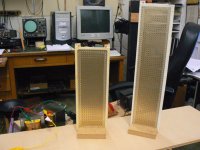
I used one of the panels from my other study and some existing baffle building blocks rather than take the time to build anything specific for the AMT test. The test panels were built using thin uninsulated perforated aluminum, 1/16" 3M foam tape, 6 micron film, and 1E9 ohm/sq Licron coating. The stators are intentionally uninsulated, and the bias voltage run fairly low at 1.8kV to aid in day to day measurement consistency with varying humidity and temperature conditions.
I use LAUD and PRAXIS measuring systems with B&K electrostatic microphone. For near field measurements of ESLs, I usually use a cheaper calibrated condenser mic to avoid the chance of damaging the expensive B&K mic capsules with a HV arc.
Measurements are complete. Test results are quite definitive, I think.
I will post the data later this afternoon along with some additional thoughts on ESL AMTs.
I have been in the midst of an ongoing series of experiments involving the resonant interaction between ESL panels of different sizes, aspect ratios, tensions etc. Also included in this study is the affect of air loading induced on the panels by baffles.
The AMT test is actually kind of a detour for me, but I figured I might learn something useful...and I DID.
I used one of the panels from my other study and some existing baffle building blocks rather than take the time to build anything specific for the AMT test. The test panels were built using thin uninsulated perforated aluminum, 1/16" 3M foam tape, 6 micron film, and 1E9 ohm/sq Licron coating. The stators are intentionally uninsulated, and the bias voltage run fairly low at 1.8kV to aid in day to day measurement consistency with varying humidity and temperature conditions.
I use LAUD and PRAXIS measuring systems with B&K electrostatic microphone. For near field measurements of ESLs, I usually use a cheaper calibrated condenser mic to avoid the chance of damaging the expensive B&K mic capsules with a HV arc.
Measurements are complete. Test results are quite definitive, I think.
I will post the data later this afternoon along with some additional thoughts on ESL AMTs.
Attachments
ESL AMT Viability Test (Part 2)
It is kind of funny how seeing a bit of experimental data can vastly improve ones ability to understand what they are reading. The behavior of slot loaded pleats is actually taught in both the Heil and Williamson/Walker patents. (US3636278, US3008013) For transducers whose moving mass is essentially made up of the airload on the diaphragm, the concept is rather simple. The vibration amplitude of the slot loaded diaphragm is reduced by the ratio of the slot width to the slot depth. Hence the name "Air Motion Transformer"? As a result, the acoustic output is reduced by this ratio as well. Assuming minimal viscous losses in pumping the air in and out of the slot, the output for one pleat will be reduced by 20*LOG(width/depth) dB relative to the same panel in free air.
I constructed 4 different slots for both Case (B) & (C).
Slot Depth (in) ... Slot Width (in) ... Ratio ....... SPL for one pleat
4.0 .................. 1.750 ............... 0.438 ..... -7.2 dB
4.0 .................. 1.000 ............... 0.250 ..... -12.0 dB
4.0 .................. 0.625 ............... 0.156 ..... -16.1 dB
4.0 .................. 0.250 ............... 0.063 ..... -24.1 dB
I believe the measured data supports the theory, especially considering the crudeness of the apparatus.
Yes, duct tape might have been involved.
The first plot compares Case (A) with and without baffle extensions. The expected dip and hump are seen along with the LF boost resulting from delaying the onset of dipole front to back cancellation. If we can restrict our SPL comparisons to the 1.0 – 1.5 kHz range we should be able to avoid having to decipher the possible differences from baffle effects, HF beaming for Case (A), and HF cavity resonances from the slot loaded pleats for Case (B) & (C).
The next 4 plots compare Case (A) to (B) & (C) for the 4 slot geometrys summarized above. As Keith’s intuition led him to believe, the diagonal pleats are clearly superior to the parallel pleats in that the onset of cavity resonance is much less abrupt and pushed higher in frequency. Looking at this data, I think that the reduction in SPL follows the theory quite well considering the experimental and construction tolerances. Others may interpret the data differently.
Looks like I need to continue this in the next post to attach another plot...
Attachments
Last edited:
ESL AMT Viability Test (Part 2) continued
The last plot is a comparison of the near field response for Case (A) with and without baffle extensions, and Case (C) with ¼” slot. Note how simply adding 4” baffle wings to an ESL panel adds airload on the diaphragm and reduces the fundamental resonance (Fs) of the panel. Case (C) with ¼” slot increased the airload on the panel by 16 so we would expect the panel Fs to drop by a factor of 4. This is very nearly the case. The slot does damp the many diaphragm resonance modes somewhat, but not nearly as well as simple application of resistive damping with cloth mesh attached to the stators.
The last plot is a comparison of the near field response for Case (A) with and without baffle extensions, and Case (C) with ¼” slot. Note how simply adding 4” baffle wings to an ESL panel adds airload on the diaphragm and reduces the fundamental resonance (Fs) of the panel. Case (C) with ¼” slot increased the airload on the panel by 16 so we would expect the panel Fs to drop by a factor of 4. This is very nearly the case. The slot does damp the many diaphragm resonance modes somewhat, but not nearly as well as simple application of resistive damping with cloth mesh attached to the stators.
Attachments
ESL AMT Viability Test (Part 3)
So, where does this leave the idea of an ESL AMT?
Here are my current thoughts on the subject.
ESL AMT woofer:
As Williamson/Walker point out in their patent, the AMT principal could be used to great advantage is ESL woofer design. Suppose we wanted to construct a high excursion ESL woofer measuring 4” wide, 60” tall with ¼” air gaps. Driving this ESL woofer to its excursion limits would require an extremely high bias voltage along with an enormous step up ratio for the driving transformers; making this design difficult to implement.
Now, suppose we replaced the one high excursion ESL panel with a 4 slot diagonal AMT(slot depth 4”, slot width 1”). We would have the same frontal area as the high excursion ESL woofer, but each of the pleated ESL panels would only need a 1/16” gap to create the effective ¼” excursion of the ESL woofer panel they replace. Voltages for driving ESL panels with 1/16” gaps are easily obtained. And, even though all of panels would need to be driven in parallel, the load impedance seen by the amplifier would not be problematic if we restrict the HF limit of the ESL AMT woofer.
As Heil mentions in his patent, a further advantage of the AMT woofer would be that total kinetic energy due to the motion of all of the AMT diaphragms would be less than that of the single high excursion ESL woofer by a factor of 4. So, less vibration induced into the ESL frame and baffles.
The possibilities here are quite intriguing…
Now that I know what I am looking for, I see that Baxandall suggested this exact concept, to allow the use of smaller air gaps in woofers, at the beginning of Section 3.2.9 of his ESL paper; I just didn't understand what he was saying. As a side note, in this same section he also suggests the use of double diaphragm / triple stator construction as a way to increase the available Force per unit area in an ESL. Martin Logan has used this construction (Dual Force I think they call it?) in their CLX full range ESL. There are also two patents that I know of for this concept, US3136867 & US3941946.
ESL AMT tweeter:
It will work, but I don’t see any advantages….only disadvantages.
Since diaphragm excursions are small and diaphragm materials are readily available that are light enough not to limit the HF response, two of the major advantages of AMTs are not needed by ESL tweeters.
Construction would be difficult with the close tolerances required. The net result is no appreciable gains in efficiency or dispersion. Also, the load impedance on the driving amplifier would be more demanding with multiple panels driven in parallel.
I think in the end, better results would be had if you simply replaced the ESL AMT tweeter assembly with a single ESL panel having the same frontal area as the sum of the AMT slot widths.
And now...I need to go cut the grass before it starts raining.
Last edited:
- Status
- This old topic is closed. If you want to reopen this topic, contact a moderator using the "Report Post" button.
- Home
- Loudspeakers
- Planars & Exotics
- Electrostatic AMT?