OK, I've had a bit of time to think on servoless centering
for the half baked wave motion version.... My suggestion
about tapering the electrical width of the stators maybe
varies the impedance and/or motor strength, but I don't
see how it looks or act much like a mechanical spring.
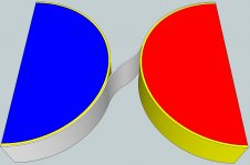
Got a new half baked idea: Supposin we were to curve both
stator surfaces slightly? So's gap in between is shortest near
the middle of the device. Now the length of a crossing peel
varies with the displacement, and subtracts from the overall
capacitance stuck to the stators, causing both physical and
electrical tensions to rise. Stator capacitance becoming our
spring we were needing?
Hmmm, yah, maybe.
In case you don't know about it, here is a great web site: recent 3
What about extending the rear chambers with deep grooves and sealing them shut, or terminating all the rear openings en mass into a single small cavity? The confined air would create restoring force. As with a small box enclosure that houses a high displacement driver, the restoring force will not be perfectly symmetrical inward vs. outward, but should be approximately symmetrical below some small displacement. Plus, you could stuff the rear box or grooves part way with some fluff to kill cavity resonances, and maybe cover the rear openings with a textile to provide some damping.
But, as ever, first the motor has to work. Let's say one side is indeed repelling and one side attracting. Now the signal starts to change polarities. What if the newly repellent side simply flings its bit of membrane away, while the other side only just starts to move? This seems possible, because that entire repellent surface will experience its full repulsive force immediately, but the other side can only apply attractive force to a thin line where the membrane meets the wall, and this line will move gradually. On the other hand, if the side that is supposed to repel can not do so because of deposited or induced charge from its contact history, and can merely resist peeling less than it would have if the drive polarity had not changed, then the part that crosses the slot might move in a manner that represents the signal.
As long as the driving signal is less than the field, I don't see
how you could ever run into repulsion? Strictly tug-o-war...
I was thinking that the signal would be bipolar. Do you mean the signal is DC-offset so that its polarity always opposes the membrane polarity? This is interesting, but a pull-pull arrangement will sacrifice considerable efficiency, and I think beyond that, charge transfer and induction from physical contact is then more likely to resist movement.
I figure since stuck ribbon appears always equidistant from both stators,
Ribbon Voltage should be exactly half whatever you set up for the field???
Drive Coulombs in or out, ribbon moves to keep the Voltage from changing.
How then does a static charge transfer???
Voltage doesn't rise or fall in either capacitor till you hit either XMAX and/or
the the ribbon is heavily air loaded and can't move. Unless we do the curved
stator thing, then maybe a little arises from rising tension??? Not really sure.
That IS the whole reason the ribbon moves. Keep the voltage from changing.
Cause if Volts did change (one cap temporarily stronger than the other) that
would pull the ribbon to find a new center where Voltage is again in balance???
If the voltage in both caps are equal, the tension per surface area is equal,
the tension under each (identical shaped?) meniscus is equal??? The position
of the ribbon to maintain that balance is what slides back and forth!
Or so the theory...
I'm figuring one stator might be covered in dielectric, and then the far side
of the ribbon covered the same. I have Kapton tape and aluminum foil on
hand... There is no reason we can't cover both stators and let the foil be
just a bare foil, cept that doesn't seem mechanically too strong? Or is a
bare foil a lot stronger than I think?
Last edited:
Maybe a picture would help?
I dunno that both dielectrics would be stationary as drawn..
If it makes the ribbon stronger to face one side and leave
that side's stator bare instead??? Again, I got Kapton tape,
so my thinking is biased by materials on hand...
I also sort of doubt the needed curves would be quite so
pronounced. Was just easier for me to draw big circles...
Attachments
Few, thanks for that, I was about to mention similar things in a post that I have been working on.
Glad you found it pertinent. I've typed and deleted a few messages before posting because I've not been sure they were of use or interest.
Mmhh, no – don't think so, Few.
The two cases, mic versus speaker are fundamentally different in this respect.
Sorry--I'm not sure what you're saying here. The two cases are different in what respect?
I would agree though to your arguments *if* you take the challenge to construct a mic with *vacuum* behind the membrane.
In this – rather academic – case you are spot on to match the diaphragm's impedance to that of the air so that the waves arriving do not get reflected.
I'm afraid you lost me here. Why would the presence of a vacuum transform the argument? Clearly it would change the balance of forces on the diaphragm, but I'm not following your argument about how this is pertinent to the role of impedance matching.
...all that counts is to make the ratio of "air load" veeeeery large with respect to "membrane mass"
If we push this to the conceptual limit, are you arguing that a massless diaphragm would be the ideal? I would argue that a massless diaphragm wouldn't be able to generate any sound. Perhaps I'm misunderstanding your intent.
I hope this isn't a digression from the original purpose of this thread. I meant to push on this impedance argument because I think it's fundamental to the feasibility of the ES-AMT.
Few
Last edited:
Masslessness
A completely massless diaphragm would be a completely virtual barrier to the air. If it also imparts zero damping or spring force of its own, the only load would be the air, and any power that is put into the system will serve to create sound. You could say there is an infinite impedance mismatch, but it is in the sense that improves efficiency. This is analogous to an amplifier with zero output impedance driving a non-zero impedance load, where all voltage will appear across the load, all power will be dissipated in the load. The efficiency of such a system is 100%.
The impedance of a real transducer will be non-zero due to practical considerations, namely actuator and piston mass, elastic restoring force, damping in its elastic recovery characteristics, its mounting structure, etc., and will thus have an impedance of its own, potentially a quite complicated one, such as a cone speaker has.
In a mechanical device, such as a transducer, mass is a reactive element (creates inertia) and is analogous to inductance in the electrical domain. In a transducer, the force on the piston/actuator is analogous to voltage, and motion is analogous to current. As current into an inductor under the influence of voltage encounters reactance during changes in voltage, a piston's motion under the influence of force encounters inertia.
Due to mass, as the frequency increases, mechanical resistance increases, just as the electrical resistance of an inductor increases with increasing frequency.
In a typical ESL, all elements of impedance other than mass are of relatively low order. It is usually arranged that the mass is such that its impedance only begins to approach the impedance of the air at the top of the audio spectrum. Below this frequency (and above resonance), the membrane acts more or less as an ideal virtual barrier to the air. (Note: My use of the ESL as a subject here is not because of any opinion against AMT's.)
At the frequency where the two impedances are equal, there will be maximum power transfer, where half the power is consumed by the transducer and half by the air. (This is not the same thing as maximum efficiency for the system as a whole -- see Maximum power theorem - Wikipedia, the free encyclopedia). At this point, the efficiency is 50%, and the SPL is down 3 dB. At higher frequencies than this, the impedance of the mass exceeds the impedance of the air and progressively reduces the amount of power transferred to the air.
The spring elements that supply elastic restoring force in a transducer are analogous to capacitance in the electrical domain. The most obvious effect is that at some frequency (toward the bottom of the operating range), the mass and spring can resonate, as with a capacitance and inductance. Mechanical damping of piston motion is analogous to resistance in the electrical domain, and will reduce resonance (inertial overshoot) up to a certain point, called critically damped, and degrade efficiency to no benefit beyond that.
All of this works in reverse for generators and microphones. For a decent short article about micrrophones, see Microphone - Wikipedia, the free encyclopedia.
Thanks for the maximum power theorem link. It was helpful.
I'm still trying to reconcile the laws of conservation of energy and momentum with the idea that a massless diaphragm could generate sound in the surrounding air. I wanted to say that the energy and momentum associated with the sound had to come from the energy and momentum of the moving diaphragm, and that a massless diaphragm can't have any kinetic energy or momentum. I learned this morning, though, that sound waves have no momentum (here's a paper on that topic). Apparently you can have a flux of momentum without there being any momentum. With that new (to me) knowledge I see that the argument I wanted to make concerning the conservation of momentum is apparently fallacious. That leaves me hesitant to say much about the energy conservation argument other than admitting my confusion.
Since this has clearly become a distraction from the original point of this thread I'll not belabor it further here.
Few
I'm still trying to reconcile the laws of conservation of energy and momentum with the idea that a massless diaphragm could generate sound in the surrounding air. I wanted to say that the energy and momentum associated with the sound had to come from the energy and momentum of the moving diaphragm, and that a massless diaphragm can't have any kinetic energy or momentum. I learned this morning, though, that sound waves have no momentum (here's a paper on that topic). Apparently you can have a flux of momentum without there being any momentum.
With that new (to me) knowledge I see that the argument I wanted to make concerning the conservation of momentum is apparently fallacious. That leaves me hesitant to say much about the energy conservation argument other than admitting my confusion. Since this has clearly become a distraction from the original point of this thread I'll not belabor it further here.
Few
I'm still trying to reconcile the laws of conservation of energy and momentum with the idea that a massless diaphragm could generate sound in the surrounding air.
All that is required is a boundary that blocks the air, plus some force to move the boundary. It's not the mass and other properties of the boundary (diaphragm) that are necessary to create sound, but the mass and other properties of the air. The fact that any real world boundary must have some mass in order to exist does not mean the mass itself is needed to make sound.
A boundary with no mass is what I am referring to as a virtual boundary. A real world surface has some mass, even a 6 micron thick membrane of plastic, but it is as good as a virtual boundary up to some maximum frequency, which is where its mass begins to become a load comparable to the air that is being pushed.
I have obviously sidestepped an analysis of the air load itself, but suffice it to say that an ESL can be made so that air's mass, compressibility, and viscosity comprise a load impedance that is higher than the speaker's within the band of interest. In other words, the air consumes virtually all the power in this case.
This seems to lead naturally back to one of the central questions from the start in this thread, which has been, "What happens when the external load is increased by confining the air to a thin slot that has just one of its narrow edges communicating with the open air?"
Well, at a minimum, it should be clear that the membrane will be facing a higher load impedance. Compared to the open air case, the air mass and therefore the impedance will be multiplied by at least the ratio of depth to width of the slot, so it will take that many times more force to create the same amount of motion. There is only the same amount of force available, though, so the air will be moved by not more than the inverse of this ratio. The fact that each pair of slot walls are moving in opposition to one another will further increase the impedance, by at least a factor of two, cutting the movement by another factor of two.
Based on that, here is what I think is the best scenario situation for the case of pleats that have a 5:1 depth to width ratio:
The membrane area within each pleat is 10x what it would be if a planar membrane were just the width of the open edge of the slot.
As discussed above, the load is at least 10x what it would be if the pleats were unfolded.
At best, the amount of sound is thus equal to what it would be from a planar membrane that is just the width of the open edges of the slots. The cost of increasing the membrane area by 10x is to increase the capacitance and thereby the electrical load by 10x, with no increase in SPL.
In fact, I think this simplified analysis is optimistic by a considerable factor. It neglects air viscosity effects. These will necessarily occur, because the slots are too narrow to propagate waves at audio frequencies, so the air must be literally pumped in and out of the slots. The velocity of the air in a slot must thus increase by 10x relative to the open air case. The viscous resistance of gases increases as the cube of the velocity, so that while it may not start out as much in the open air case, whatever that is will be multiplied by 1000, and it is not inconceivable that this will then be something significant. There will also be surface drag and edge turbulence effects that further attenuate membrane motion.
Last edited:
Sorry--I'm not sure what you're saying here. The two cases are different in what respect?
I'm afraid you lost me here. Why would the presence of a vacuum transform the argument? Clearly it would change the balance of forces on the diaphragm, but I'm not following your argument about how this is pertinent to the role of impedance matching.
If we push this to the conceptual limit, are you arguing that a massless diaphragm would be the ideal? I would argue that a massless diaphragm wouldn't be able to generate any sound. Perhaps I'm misunderstanding your intent.
I hope this isn't a digression from the original purpose of this thread. I meant to push on this impedance argument because I think it's fundamental to the feasibility of the ES-AMT.
Few
Some like to orbit in theory bubbles ..
If you would like to gain some better "grip" on the subject though, I suggest to join a journey into kindergarten.
The kindergarten I think we should visit for this very topic is usually called kinematics.
What I will outline isn't the "real thing" in a scientific way but IMO should be very helpful to differentiate between the two fundamentally different cases of microphone versus loudspeaker.
Here we go:
Imagine a speaker lying on the floor and a mic that's hung - say a meter above or so.
Simple experimental setup – no?
OK, to analyse the point I want to make, assume the room to be evacuated and the many air molecules being substituted by a single ping-pong ball resting on the speaker.
Now - if you apply sufficient force to the membrane of your speaker to move forward - the ping-pong ball most likely will jump up and hit the mic.
Now we change the speakers diaphragm to be of heavy plumb – for sure we would have to beef up the amplifier to make the ping-pong ball hit the mic again – no?
Already we easily have learned the first lesson – heavy membrane no good – the lighter the membrane the better – "no mass" membrane *best*
If you are still in doubt – do the same experiment with your bowling ball instead of a ping-pong ball – you certainly will come to the conclusion that its of no benefit to make the speakers membrane mass exactly the same than that of your bowling ball !
###########
So far so good - now lets examine the case of the mic.
Imagine the same experimental setup as before and turn it into a horizontal position.
Lets assume the ping-pong ball to rest at the very rim of a table – the speaker right behind (already touching the resting ball) and the mic again say in one meter distance at front (on the table).
LOL, hope you like kidding around with balls!
Now again we apply sufficient force to the speaker membrane to shoot the ping-pong ball at the mic.
In fact - for making the conclusions I'm after - any device to accelerate the ball will do – be it a bow, a gun, a catapult or a *pure* force only (mind you - a rocked would only do in this experiment, if shut off *before* hitting the mic)
Actually, we wouldn't care, how the ball got its speed at all (but its great fun to figure out some possibilities) - there *is* speed when the ping-pong ball is hitting the mic – that's all we want to concentrate on.
Now – having proven we can aim our shooting perfectly - we step up to level two of our kindergarten game and add one extra ping-pong ball just in the middle (between speaker and mic) and also substitute the mic membrane by a third ping-pong ball.
What's gonna happen is that the ping-pong ball we shoot hits the one after ½ a meter > transfers all his impulse energy to the second ping-pong ball by loosing all its speed (actually resting roughly at the place in the middle) > whereas the second ping-pong ball will continue to transfer energy with exactly the speed of the first one > and hit the ping-pong ball membrane of our mic, transferring *all* its impulse energy to the mic .
Wow – great shot indeed!
What we have learned that way is that to transfer all energy available *completely* to the ping-pong ball diaphragm of our mic - the mic membrane *must* be the equivalent mass of the arriving "air"
Pretty simply - and - easy to test at any billiard table.
###########
QED
")
So - in technical terms the difference between mic and speaker regarding the topic of "impedance" is that in case of the mic we have to deal with *impulse transfer* whereas in case of a speaker we simply have to deal with *force accelerating some mass* (no matching needed whatsoever !!!).
You could do a similar kindergarten illustration with coupled spring mass systems to get more closely to "reality" but I find it easier to get to a widely sufficient understanding of some of the basic mechanisms that way.
Michael
Last edited:
A completely massless diaphragm would be a completely virtual barrier to the air. If it also imparts zero damping or spring force of its own, the only load would be the air, and any power that is put into the system will serve to create sound. You could say there is an infinite impedance mismatch, but it is in the sense that improves efficiency. This is analogous to an amplifier with zero output impedance driving a non-zero impedance load, where all voltage will appear across the load, all power will be dissipated in
More or less – *massless* is of no need for the first sentence!
The impedance of a real transducer will be non-zero due to practical considerations, namely actuator and piston mass, elastic restoring force, damping in its elastic recovery characteristics, its mounting structure, etc., and will thus have an impedance of its own, potentially a quite complicated one, such as a cone speaker has.
In a mechanical device, such as a transducer, mass is a reactive element (creates inertia) and is analogous to inductance in the electrical domain.
Sure, but misleading in the context - as for Few's questioning the load (meaning impedance) a speaker (in vacuum) presents to the *amplifier* was of no interest.
In a transducer, the force on the piston/actuator is analogous to voltage, and motion is analogous to current. As current into an inductor under the influence of voltage encounters reactance during changes in voltage, a piston's motion under the influence of force encounters inertia.
IMO you start to mix things here (the equivalent electric circuit with the real part) ?
In the case of dynamic speakers, force is proportional to current, whereas for a ES force is proportional to voltage.
In a typical ESL, all elements of impedance other than mass are of relatively low order. It is usually arranged that the mass is such that its impedance only begins to approach the impedance of the air at the top of the audio spectrum. Below this frequency (and above resonance), the membrane acts more or less as an ideal virtual barrier to the air.
Seen from the point of the amp – as you did before, when referring to dynamic speakers – no (lots of "impedance" from the ESL capacitor).
My critics here – you jump between points of view without telling that you are *not* referring to equal things (comparing apples and hamburegers)!
(Note: My use of the ESL as a subject here is not because of any opinion against AMT's.)
No problem as for me - I have as much love for ESL as I have for AMT
Mechanical damping of piston motion is analogous to resistance in the electrical domain, and will reduce resonance (inertial overshoot) up to a certain point, called critically damped, and degrade efficiency to no benefit beyond that.
No – the case of critical dampening is the "aperiodic border line" (right wording?) where no ringing occurs after a step impulse – it has nothing to do whether there is useful output beyond or not.
All of this works in reverse for generators and microphones.
no

Michael
Last edited:
Thanks for the tutorials David and Michael. In acoustics, instincts can often be wrong. Yes, as in electrical theory, there is maximum power transfer, and most efficient power transfer: both have their applications. Irrespective of which we use the reactances produce no sound, only load the motor. Mention of barriers, real or notional gets mentioned in Beranek's definition of acoustic impedance.
"The acoustic impedance at a given surface is defined as the complex* ratio of effective sound pressure averaged over the surface to effective volume velocity through it. The surface may be a hypothetical surface in an acoustic medium or the moving surface of a mechanical device"
* Same meaning as in electrical complex impedances.
The forces available from ES means were always going to be questionable when considering the AMT. If we equate transformation with leverage, where we consider force and motion, the AMT has the leverage around the wrong way from the motor's perspective.
Few, Your idea is a real brain twister, hard to know where to start particularly when the heat gets to you. South Australia is having the kind of heat wave we normally get in January/February.
Keith
South Australia is having the kind of heat wave we normally get in January/February.
As I recall, the prescription is 2 pints with every meal. Side effects may include jolliness, so operate heavy machinery only if it's fun. Increased risks when surfing are outweighed by decreased attractiveness to sharks from increased tendency to bite back. Track down forecaster if symptoms worsen or persist for more than 1 week.
Few: Your drawing was helpful. I'm sure I'm not the only one who'd be fascinated by the result if you fabricate a bare bones model. Strikes me that you could start with plastic wrap from the kitchen for the membrane, bare sheet metal or a couple of lengths of pipe for the stators, and DC from a multiplier to coax motion from the transverse bit. The scale is not really important at this point. You might have an exciting moment in store.
1) I am not Few. And I am sure he would be equally relieved to hear it...
2) How should this plastic wrap be made conductive??? It must bridge the halves of the cap.
Helpful suggestions on the merits of various conductive films here:
http://www.stopabductions.com/dev.htm
2) How should this plastic wrap be made conductive??? It must bridge the halves of the cap.
Helpful suggestions on the merits of various conductive films here:
http://www.stopabductions.com/dev.htm
Last edited:
1) I am not Few. And I am sure he would be equally relieved to hear it...
LOL. Sorry, both of you.
2) How should this plastic wrap be made conductive??? It must bridge the halves of the cap.
I would try it first with no conductive coating. It may be that simply increasing the voltage on one stator and decreasing it on the other will create motion. Worth a try, I think.
You could get sufficient conductivity for the purpose from dilute dish soap -- wipe a bit of it on and let it dry. (Some DIY ESL people use this as a membrane coating, but I would not recommend it for the long term.)
If you want to experiment with insulating the stators and applying a bias to the membrane, some copper shielding tape applied to the film before coating it would do for a contact.
[Helpful suggestions on the merits of various conductive films here:
Development
Those guys are crazy! I thought everyone knew that denim and feathers make the best thought shield. I guess it's the old absorption vs. dispersion argument so common on audio and alien abduction forums. Anyway, that's what I use whenever I want some privacy, and I know it works because once when I took it off, I learned I was busted -- the ET's told me to stop using it or else.
Not relieved in the least. (See below.)I am not Few. And I am sure he would be equally relieved to hear it...
I think my brain was twisted before this all started.Few, Your idea is a real brain twister

Key (embarrassingly simple) point I was missing: The diaphragm must have mass in order to create sound if the diaphragm is moving only as a result of its own inertia. If it's constantly driven by some force, then my concern about a massless diaphragm having zero kinetic energy is baseless. Speaker diaphragms are always driven by a force. I was too distracted by images of those executive desk toys with the suspended ball bearings that smack into each other and demonstrate the importance of conservation of energy and momentum. Not pertinent.
Once I removed my head from my rear-facing bass port it was all much clearer. It's a good thing I play with speakers primarily because it gives me an excuse to learn stuff. If I did it because I wanted to pump up my ego I'd be failing miserably. Sorry to have inflicted my confusion on everyone else.
Few
ESL AMT Viability Test
I have been following this thread with much interest, and little to add, as my knowledge of AMTs is quite limited. I have read the applicable Heil Patent US3636278 and the author speaks of the AMT allowing the use of heavier diaphgrams for the same high frequency cut-off. I didn't specifically see any discussion about impedance matching as a goal. Also, I found it interesting that the words "air motion transformer" are never mentioned. They are, however, used several times in his later patent on low frequency transducers built with similar concepts, US4039044.
I also noticed in the Walker Patent US3008013, figures 7, 8, & 9 do appear to be similar in concept to an AMT. So, at least ESL AMTs are mentioned in patents by at least one known respectible engineer. Actually, Keith, doesn't figure 7 look exactly like what you were suggesting back in post #90?
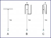
OK. On to the viability test. As David stated in post #149 "...one of the central questions from the start in this thread, which has been, "What happens when the external load is increased by confining the air to a thin slot that has just one of its narrow edges communicating with the open air?"
Well, I have a few 3"x12" ESL test panels laying around and I was thinking of running the tests pictured in the attached figure on Saturday. Case (A) would be the reference, your basic ESL. Case (B) would be for parallel pleats, and Case (C) with diagonal pleats as Keith suggested. I would vary dimension "d" over a considerable range to get some trend data as the AMT "transformation ratio" is varied. For ease of setup, I figured I would use just one pleat.
A couple of questions:
1) Do you guys think a test of this scale would prove or dissprove the viability of the ESL AMT idea? I understand due to the size of the panel that the high frequency response would still be in question, but I think it would give us some answers as to whether an ESL can drive an AMT.
2) For Case (B) & (C) should I place the mic 1 meter from the center of the ESL panel? or 1 meter from the slot opening; to get an apples to apples comparison with the reference case
3) Obviously, if Cases (B) & (C) produced the same SPL as the reference for very small slot sizes this would be a good thing. But, since this is just one pleat and an ESL AMT would be made up of multiple, what results would you consider to by promising? -6dB from reference? -12dB? How much loss for a single pleat before the ESL AMT idea is no longer viable.
...one of the central questions from the start in this thread, which has been, "What happens when the external load is increased by confining the air to a thin slot that has just one of its narrow edges communicating with the open air?"
I have been following this thread with much interest, and little to add, as my knowledge of AMTs is quite limited. I have read the applicable Heil Patent US3636278 and the author speaks of the AMT allowing the use of heavier diaphgrams for the same high frequency cut-off. I didn't specifically see any discussion about impedance matching as a goal. Also, I found it interesting that the words "air motion transformer" are never mentioned. They are, however, used several times in his later patent on low frequency transducers built with similar concepts, US4039044.
I also noticed in the Walker Patent US3008013, figures 7, 8, & 9 do appear to be similar in concept to an AMT. So, at least ESL AMTs are mentioned in patents by at least one known respectible engineer. Actually, Keith, doesn't figure 7 look exactly like what you were suggesting back in post #90?
OK. On to the viability test. As David stated in post #149 "...one of the central questions from the start in this thread, which has been, "What happens when the external load is increased by confining the air to a thin slot that has just one of its narrow edges communicating with the open air?"
Well, I have a few 3"x12" ESL test panels laying around and I was thinking of running the tests pictured in the attached figure on Saturday. Case (A) would be the reference, your basic ESL. Case (B) would be for parallel pleats, and Case (C) with diagonal pleats as Keith suggested. I would vary dimension "d" over a considerable range to get some trend data as the AMT "transformation ratio" is varied. For ease of setup, I figured I would use just one pleat.
A couple of questions:
1) Do you guys think a test of this scale would prove or dissprove the viability of the ESL AMT idea? I understand due to the size of the panel that the high frequency response would still be in question, but I think it would give us some answers as to whether an ESL can drive an AMT.
2) For Case (B) & (C) should I place the mic 1 meter from the center of the ESL panel? or 1 meter from the slot opening; to get an apples to apples comparison with the reference case
3) Obviously, if Cases (B) & (C) produced the same SPL as the reference for very small slot sizes this would be a good thing. But, since this is just one pleat and an ESL AMT would be made up of multiple, what results would you consider to by promising? -6dB from reference? -12dB? How much loss for a single pleat before the ESL AMT idea is no longer viable.
Attachments
Last edited:
Nice diagrams, Bolserst. Looks to me like your experiment will generate interpretable data as is.
Now, just a suggestion, but I would try something simpler for a start: Lay a panel down on a workbench or table and slide it partially off the edge. Whatever portion is left in contact with the surface will be incapacitated, at least in band, so this is a way of varying the effective area of the radiator. Take a second hard surface and vary its position relative to the operating part of the panel while playing pink noise, and just listen to the effect. You can do this over the top or under the bottom, and I think it will be most interesting at first to do it under the bottom while listening from the top. Then, if you find the results encouraging, proceed with the experiment you propose.
Unless Keith has already tried this . . . Keith?
Bolserst – brave man you are!
The exact distance of the mic would not be of big concern as ~1" difference wouldn't do much SPL variation. You can always do a sanity check of course...
The setup suggested in this simple form would not provide any usable result though, as the overall *width* of the speaker is of big influence.
So you will have to make sure *at least* that in any case the baffle is of the same size – meaning – you have to put any arrangement into a baffle of the same size.
To further reduce the effects of different path length, I'd suggest to make the baffle minimum twice the width of the pure ESL.
Most certainly F-res will drop and you will get the irregularities from comb filters in upper part.
Basically you get an OB / Ripole arrangement and this one isn't any easy to compare with a baffleless ararngement, look here:
http://www.diyaudio.com/forums/mult...fle-dipole-beyma-tpl-150-a-8.html#post1974098
Read through some of the previous and following posts as well.
I'm definitely looking forward to your results.
#########
David's suggestion's of a quick and dirty try are way off in its ancillary conditions to be any useful.
Again, David – learn the basics!
(No doubt you are a wonderful "man of praxis" but your mixed up theories and superficial "sales-man-level" explanations constantly lack "in depth" understanding of more subtle issues)
So, having all the skills and materials – why not making an 10:1 ratio multi pleat prototype for us?
You wouldn't have to go with Keith's arrangement – Bolserst' arrangement would do with multiple single ESL's for a prove of concept as well...
Michael
Last edited:
Calm down, mige0.
With a bit more open mindedness, you'd see the point of my suggested test is to quickly illuminate the most basic question of whether confining the output of an ESL will increase the load to the point of killing the sound or not, and give whoever tries it a feel for the interesting interference effects that can occur with various degrees and types of confinement.
Also, the data from both mine and Bolsersts's experiments can be extrapolated to smaller geometries and multiple slots, if one would wish to do so, which one may not.
- Status
- This old topic is closed. If you want to reopen this topic, contact a moderator using the "Report Post" button.
- Home
- Loudspeakers
- Planars & Exotics
- Electrostatic AMT?