WrineX, thanks for your continuing interest in the subject. By closed stators you presumably mean non perforated. Acoustically, it probably does not matter if the stators are plain sheet metal or perforated. I always had in mind non perforated as we gain some extra force that way.
The instantaneous air pressures on either side of the stator are going to be very similar, so if you had perforations they would not be doing anything usefull like they would in a conventional ESL. The pleat dimensions are "acoustically small" so we should get no phase cancellation effects, besides, it could be argued that a conventional AMT has no solid barriers between the pleats, yet it works.
You are correct in assuming you need just one bias supply.
Keith
WrineX, sadly, no matter whether it is Walker, Williamson or some other ESL luminary filing a patent application there is no guarantee that it actually works!
Keith
Nope I know, and this is one of those that I think I won't work or at least not much better then a plane esl or amt. still worth a try sometimes
I think that it could work as a sub woofer system, but that is about it as the labor and material's costs would be rather high.
I have calculated some displacement figures before and in order for it to be effect your talking about a very high section count.
Even with moderately sized panels of say 6" x 24" or 36" long you would need at least 8 to 12 sections or even 16 or more to be as effective as one or two 8"-12" woofers.
It is all about Displacement at this point.
But I think that it may be possible to create a small package with an effective amount of bass and possibly very clean sounding, but not considering the labor and materials cost.
I had been thinking about this for the last 10 years or so but I just don't have the materials or the time in the labor to give it a try yet.
Imagine a 6" x 6" x 12" area box shape having the same effective displacement of two 8" subs, but again you are talking about at least 12 to 16 sections if not 24 if you could make them fit in a 6" wide space!!
FWIW")
jer
I have calculated some displacement figures before and in order for it to be effect your talking about a very high section count.
Even with moderately sized panels of say 6" x 24" or 36" long you would need at least 8 to 12 sections or even 16 or more to be as effective as one or two 8"-12" woofers.
It is all about Displacement at this point.
But I think that it may be possible to create a small package with an effective amount of bass and possibly very clean sounding, but not considering the labor and materials cost.
I had been thinking about this for the last 10 years or so but I just don't have the materials or the time in the labor to give it a try yet.
Imagine a 6" x 6" x 12" area box shape having the same effective displacement of two 8" subs, but again you are talking about at least 12 to 16 sections if not 24 if you could make them fit in a 6" wide space!!
FWIW
jer
Last edited:
Hi,
a Patent on a AMT-ESL in 2013??
Come on .... fire those unknowledgable officers in the patent bureaus if they can´t do a proper patent search.
Obviously the Sony treatise is only about to hinder anyone else to generally be able to produce AMT-like ESLs using CAD/CAM manufacturing methods, resp. the whole production process.
The part about the ESL functioning itself is rather weird .... after a first short read I think it is describing a array of SE-ESLs as there´s a polarizing voltage between each membrane and each electrode.
Each pleat of the array consists of two membrane parts and two electrode parts.
Only the membrane parts receive the audio signal.
Hence the attracting forces will act mainly between a membrane part and the associated electrode part.
In contrast to the original (magnetic) AMT and the other patent descriptions, the electrode parts are obviously not fixed to the membrane parts, but function like a stator --> singleended esl.
The polarizing voltages are apllied to the associated membrane parts and electrode parts ... it can differ between each pair, resp. each pleat or may be equal.
There´s no audio signal applied between the different legs of a pleat (sounds weird?? It is weird! )
)
The neccessarily required spacers are not described in the patent text ... hence the object won´t work at all
It very much looks to me as if some poor chap without proper knowledge got a description of the magnetic AMT and had to translate it into ESL.
Probabely a lawyer whose task it was to claim anything possible and probable to hinder anyone else to produce a ESL-AMT.
In that it equals Sander´s late PCB-stator patent that copied Beverdidge´s well known patents apart from the CNC-manufacturing.
It looks not like a defence of Sonys own intellectual property but like a measurement to prevent others to market his/her intellectual property.
Simply disgusting
One of the earliest patents I found features a slightly different membrane and stator structure, though the basic idea is very similar.
Its US 2,864,899, from Dec 16th, 1954, simply named ´Transducer´.
References cited date from the late 20s into the early 30s.
Second there´s a real AMT structure patented to Mivoc Audio Systems under German patent number DE 4041 544 A1 (int. Cl.: H04R 19/02).
Title: ´elektrostatischer Lautsprecher´ (electrostatic loudspeaker).
It dates from June 25th, 1992.
Third, another German patent ´Electrostatic Loudspeaker´, DE 195 03 728 A1, from Aug. 8th, 1996, filed to Mr. Warkentin.
All three describe ESL structures that are technically plausible, complying with physics.
jauu
Calvin
a Patent on a AMT-ESL in 2013??
Come on .... fire those unknowledgable officers in the patent bureaus if they can´t do a proper patent search.
Obviously the Sony treatise is only about to hinder anyone else to generally be able to produce AMT-like ESLs using CAD/CAM manufacturing methods, resp. the whole production process.
The part about the ESL functioning itself is rather weird .... after a first short read I think it is describing a array of SE-ESLs as there´s a polarizing voltage between each membrane and each electrode.
Each pleat of the array consists of two membrane parts and two electrode parts.
Only the membrane parts receive the audio signal.
Hence the attracting forces will act mainly between a membrane part and the associated electrode part.
In contrast to the original (magnetic) AMT and the other patent descriptions, the electrode parts are obviously not fixed to the membrane parts, but function like a stator --> singleended esl.
The polarizing voltages are apllied to the associated membrane parts and electrode parts ... it can differ between each pair, resp. each pleat or may be equal.
There´s no audio signal applied between the different legs of a pleat (sounds weird?? It is weird!
)The neccessarily required spacers are not described in the patent text ... hence the object won´t work at all
It very much looks to me as if some poor chap without proper knowledge got a description of the magnetic AMT and had to translate it into ESL.
Probabely a lawyer whose task it was to claim anything possible and probable to hinder anyone else to produce a ESL-AMT.
In that it equals Sander´s late PCB-stator patent that copied Beverdidge´s well known patents apart from the CNC-manufacturing.
It looks not like a defence of Sonys own intellectual property but like a measurement to prevent others to market his/her intellectual property.
Simply disgusting
One of the earliest patents I found features a slightly different membrane and stator structure, though the basic idea is very similar.
Its US 2,864,899, from Dec 16th, 1954, simply named ´Transducer´.
References cited date from the late 20s into the early 30s.
Second there´s a real AMT structure patented to Mivoc Audio Systems under German patent number DE 4041 544 A1 (int. Cl.: H04R 19/02).
Title: ´elektrostatischer Lautsprecher´ (electrostatic loudspeaker).
It dates from June 25th, 1992.
Third, another German patent ´Electrostatic Loudspeaker´, DE 195 03 728 A1, from Aug. 8th, 1996, filed to Mr. Warkentin.
All three describe ESL structures that are technically plausible, complying with physics.
jauu
Calvin
Last edited:
Hi Calvin, I agree that it looks like single ended operation. The "electrodes" seem to be what I would call perforated stators. Presumably the membrane is a non segmented film with a resistive coating.
I find it hard to take this design seriously. The obfuscation in the text seems to reach a new high even if the subject device falls short of something that is capable of working!
Keith
I find it hard to take this design seriously. The obfuscation in the text seems to reach a new high even if the subject device falls short of something that is capable of working!
Keith
Wow...didn't mean to get Calvin so riled up
Like the Sanders document, it is just a patent APPLICATION. (ie not approved)
It would be a pretty sad state of affairs if the Sony application got approved with all the prior art on the ESL AMT configuration we discussed earlier in this thread. Then again, the Final patent for inverted ESL configuration was approved even with prior art dating back to 1934 by none other than E. W. Kellogg of dynamic driver fame.
My reason for bringing it up, was that it could mean some of Sony's current or soon-to-be released electronic device may contain ESL AMTs for use with low voltages which might be interesting to experiment with.
Hi,
).
It´s daily exyperience that court trials are busted and criminals leave the court as free men because of some minor formal incorrectness.
When in the law business form matters more than substance than something went seriously wrong.
When the original idea of a patent to secure the patentee the economical exploitation of his new idea against copiers changes to a mechanism allowing to impeach and take to court anybody else who wants to put his new idea to market, You know something went seriously wrong.
See for example, Sony didn´t invent the Walkman .... nor did they ever compensate the real inventor.
They just sent in their stinky filthy army of lawyers, paid from the earnings of the product that´s idea they copied.
jauu
Calvin
I´m afraid that this will happen all too soon, as it obvious that for patents nowadays it seems fully irrelevant if there´s any flesh or realism to it, as long as it is written formally correct (damn lawyersIt would be a pretty sad state of affairs if the Sony application got approved with all the prior art on the ESL AMT configuration we discussed earlier in this thread.
).It´s daily exyperience that court trials are busted and criminals leave the court as free men because of some minor formal incorrectness.
When in the law business form matters more than substance than something went seriously wrong.
When the original idea of a patent to secure the patentee the economical exploitation of his new idea against copiers changes to a mechanism allowing to impeach and take to court anybody else who wants to put his new idea to market, You know something went seriously wrong.
See for example, Sony didn´t invent the Walkman .... nor did they ever compensate the real inventor.
They just sent in their stinky filthy army of lawyers, paid from the earnings of the product that´s idea they copied.
jauu
Calvin
Ohoh gone post on a thread that is years old, i knew i´ve seen it somewhere
so yesterday night my brain rambled about the EAMT once more....
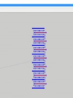
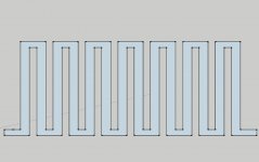
i noticed the first posts plan was using the foils as stator and feed audio onto it as well. really neat idea, not yet clear if it panned out. but i was thinking more around these lines. (see pic1) similar also posted before. i've seen the measurements from Bolserst, what i dont get is , every form of a cavity destroyed output ? in this a ESL version , since my magnetic amts do function better then a foil that has the same size the amt contraption would take up.
Then ofcourse the dips and peaks created by the cavity, or the fact it emits top end over a size bigger then the halve a wavekength are a problem to. but i thought if is use these solid stators. im free segment them depth wise.
Its weird but in this case i could segment the EAMT in 3 directions. vertically like most ESL's , horizontal and depth. depth could be usefull , so having a bigger low pas the deeper you go into the pleat. ?
just a brain fart
since the Bias track is continuous, i wonder if the repelling force is an issue... although they are 6 mm appart in this design.
To make the vertical stators i thought about making it from 0.5mm PCB strips (might need to add an ofsset since it is single sided)(could be any solderable metal thin enough as well) then cut some vertical strips 2mm thick and solder them on to the vertical ones to hold the correct spacings and be ably to hold the whole thing in front of the foil,
Gone be allot of juggling in all directions to align , main problems i see tolerances! its easy to create a fault somewhere (like PCB not straight enough , or one of the folds)
i would etch a metalized 5 micron foil for the bias track to try.. but this time i wait a little someone might say it does not work !!! because .. and ... so i dont waste any time this time
so yesterday night my brain rambled about the EAMT once more....
i noticed the first posts plan was using the foils as stator and feed audio onto it as well. really neat idea, not yet clear if it panned out. but i was thinking more around these lines. (see pic1) similar also posted before. i've seen the measurements from Bolserst, what i dont get is , every form of a cavity destroyed output ? in this a ESL version , since my magnetic amts do function better then a foil that has the same size the amt contraption would take up.
Then ofcourse the dips and peaks created by the cavity, or the fact it emits top end over a size bigger then the halve a wavekength are a problem to. but i thought if is use these solid stators. im free segment them depth wise.
Its weird but in this case i could segment the EAMT in 3 directions. vertically like most ESL's , horizontal and depth. depth could be usefull , so having a bigger low pas the deeper you go into the pleat. ?
just a brain fart
since the Bias track is continuous, i wonder if the repelling force is an issue... although they are 6 mm appart in this design.
To make the vertical stators i thought about making it from 0.5mm PCB strips (might need to add an ofsset since it is single sided)(could be any solderable metal thin enough as well) then cut some vertical strips 2mm thick and solder them on to the vertical ones to hold the correct spacings and be ably to hold the whole thing in front of the foil
, Gone be allot of juggling in all directions to align
, main problems i see tolerances! its easy to create a fault somewhere (like PCB not straight enough , or one of the folds)i would etch a metalized 5 micron foil for the bias track to try.. but this time i wait a little
someone might say it does not work !!! because .. and ... so i dont waste any time this time Attachments
Last edited:
Hi WrineX and others
I am still in the land of the living! It is hard to believe that it was 20 years ago when I came up with ideas for an ESAMT. Have to say that I have not had any new insights into furthering the cause.
Insoluble problems that remain include the necessity to have the pleat halves under tension leading to resonances. Also the necessary spacers that the membrane wraps around create pockets of "dead air" reducing the volumetric efficiency.
I think you are wise to experiment with a stator version. The statorless version presents problems making contact with the pleats. Even were you to get this right for a certain amount of tension it is likely to be miss aligned as you vary the tension.
A thought I have had re conventional electro magnetic AMT's is to introduce stators between the pleats in the form of very thin neodymium magnets where they are polarised across the thin dimension. Thus we have a flux running from one "stator" to the next which the pleat halves are immersed in. Of course the acid test is that it has to conform to the "left hand rule of electromagnetism" to get AMT motion. This would be suited to low frequency AMT's with larger pleat depths; if it works.
Keith
Hi WrineX and others
I am still in the land of the living! It is hard to believe that it was 20 years ago when I came up with ideas for an ESAMT. Have to say that I have not had any new insights into furthering the cause.
Insoluble problems that remain include the necessity to have the pleat halves under tension leading to resonances. Also the necessary spacers that the membrane wraps around create pockets of "dead air" reducing the volumetric efficiency.
I think you are wise to experiment with a stator version. The statorless version presents problems making contact with the pleats. Even were you to get this right for a certain amount of tension it is likely to be miss aligned as you vary the tension.
A thought I have had re conventional electro magnetic AMT's is to introduce stators between the pleats in the form of very thin neodymium magnets where they are polarised across the thin dimension. Thus we have a flux running from one "stator" to the next which the pleat halves are immersed in. Of course the acid test is that it has to conform to the "left hand rule of electromagnetism" to get AMT motion. This would be suited to low frequency AMT's with larger pleat depths; if it works.
Keith
well i did sort of that by using magnets that where the in place of where normally the folds are. so wraping back and forth around a thin long magnet. cant say i liked the sound that came out haha. hardly any and terible to
a normal amt worked much better even with a low magnetic force. in the EAMT when stators (they are so tiny) are used the foil should be able to contain its shape with the help of some alumnium foil running horizontal every here and there. still i am afraid that the end result would be hardly any improvement
aah well we will see , i first try to make a proper magnetic version After I wrote the last paragraph I realised that it would not work as the flux direction has to be at 90 degrees to the motion to satisfy the "left hand rule"
I was going to edit my post, but the 30 minute limit had expired. I think this probably explains why your experiments did not work.
Keith
I was going to edit my post, but the 30 minute limit had expired. I think this probably explains why your experiments did not work.
Keith
After I wrote the last paragraph I realised that it would not work as the flux direction has to be at 90 degrees to the motion to satisfy the "left hand rule"
I was going to edit my post, but the 30 minute limit had expired. I think this probably explains why your experiments did not work.
Keith
i had it according the hand rule left or right
does not matter the front magnets where atracting to the back ones, just like in an amt so field was front to back then i made a ribbon that had there coil moving instead of in the length of the ribbon sideways. so when threaded the coil would sit like it would in an amt. not sure why it did not work. might take a look at it later - Status
- This old topic is closed. If you want to reopen this topic, contact a moderator using the "Report Post" button.
- Home
- Loudspeakers
- Planars & Exotics
- Electrostatic AMT?