Well this is actually MkIII, so we're talking about MkIV.... ")
This was MkI about 8 Years ago:
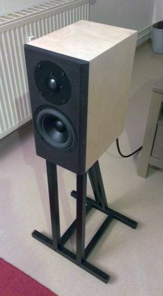
I'm not a fan of MTM / D´Appolito arrangement, but a little 2-1/2 Way TWW-Floorstander is a nice idea...
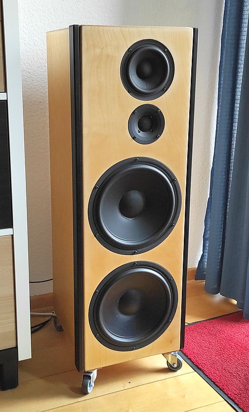
If you allow it to be a bit larger there are other options:
Best regards
Peter
This was MkI about 8 Years ago:
I'm not a fan of MTM / D´Appolito arrangement, but a little 2-1/2 Way TWW-Floorstander is a nice idea...
If you allow it to be a bit larger there are other options:
Best regards
Peter
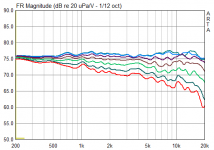
"Just some holes" has the disadvantage that the boreholes couple directly to the cabinet. Tired this before the approch with the closed concentric resonator tube:
View attachment 1105329
Blue: Without holes
Green: With holes open to the inner cabinet; The tuning frequency increases (virtual tube length decreases), and a lot of midrange dirt goes through them.
Red: With holes, but tube is wrapped with isobond acoustic felt + Gaffa Tape; a lot better, but the mechanical losses of the port are increased and so the output level decreased by ~ -1dB.
I played a bit with port resonance mitigation. Take a peek here:
https://www.audiosciencereview.com/...ies-dual-concentric.29383/page-3#post-1025993
If the opening area between the resonator/trap and the port is smaller than the area of the resonator itself the latter will not work as pure lambda/4 trap anymore but it will also have some properties of an unwanted (parasitic) Helmholz resonator that may be excited at its resonant frequency by sounds from the backside of the driver or by an effect like blowing over a bottle.Apart from that: I imagine that effect takes place on the resonant frequency of the tube resonator, but that the openings towards it behave relatively inconspicuously away from this frequency.
While the middle of the port tube will be the most effective place for the trap it might probably also work when the trap is open to the back end of the port instead and thereby omitting these effects.
Regards
Charles
If the opening area between the resonator/trap and the port is smaller than the area of the resonator itself the latter will not work as pure lambda/4 trap anymore but it will also have some properties of an unwanted (parasitic) Helmholz resonator that may be excited at its resonant frequency by sounds from the backside of the driver or by an effect like blowing over a bottle.
That is a valid theory in general, but i can´t measure or hear anything like that. The volume is so small and the holes so large in comparison that i assume that the helmholz resonance is maybe 1) very high / out of woofer´s range and 2) has a low Q and so is hard to stimulate.
While the middle of the port tube will be the most effective place for the trap it might probably also work when the trap is open to the back end of the port instead and thereby omitting these effects.
This will introduce a leakage which will lower the port's Q, decrease the virual length / increase tuning frequency und counteract the resonator's basic function as a quarter wave pipe....
Here are some final measurements (Speakers on Stand + Chair underneath = @half height of my living room, gated, ~1,2m measurement distance, measurement axis ~2cm below tweeter axis, without turntable/different angles adjusted "free hand"):
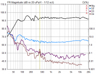
Distortion @ ~94dB (Measurement distance 33-34cm, Mic Preamp Gain -10dB so the displayed SPL is roughly correct):
(The high k2 comes from my measurement chain, probably the mic)
The little resonance @400Hz matches no geometric dimension (much too low frequency), I assume it comes from the woofer's spider or memrane tumbling.
The speaker is sensitive to stuffing of damping (too much = thin sounding fundamentals, too less = boomy), this is how it works well now:
(German "Weiche" = Xover)
Best regards
Peter
Attachments
Last edited:
The topology that I mean will not introduce any leakage nor will it counteract the resonator's function in any way. It will just act at a different position of the tube. I.e at the end instead of the middle. The reflex tube will not have any holes at all. The closed end of the resonator would be at the middle position of the tube and its open end will be at the back end of the reflex tube.This will introduce a leakage which will lower the port's Q, decrease the virual length / increase tuning frequency und counteract the resonator's basic function as a quarter wave pipe....
I don't have any drawing program with me at the moment but I can make a hand drawing if it is not clear what I mean.
Didn't you have noise issues until you enlarged the holes? I was just trying to figure out where this might have come from.That is a valid theory in general, but i can´t measure or hear anything like that. The volume is so small and the holes so large in comparison that i assume that the helmholz resonance is maybe 1) very high / out of woofer´s range and 2) has a low Q and so is hard to stimulate.
Regards
Charles
Have you tried a slash cut (60 degree angle) on the inside end, using the average total of length? These seem to work well for me on smaller BR enclosures at reducing the higher order resonances."Just some holes" has the disadvantage that the boreholes couple directly to the cabinet. Tired this before the approch with the closed concentric resonator tube:
View attachment 1105329
Blue: Without holes
Green: With holes open to the inner cabinet; The tuning frequency increases (virtual tube length decreases), and a lot of midrange dirt goes through them.
Red: With holes, but tube is wrapped with isobond acoustic felt + Gaffa Tape; a lot better, but the mechanical losses of the port are increased and so the output level decreased by ~ -1dB.
I have a question - what do these small caps (10nf parallel with 2.7uf cap in tweeter, 1.5uf parallel with 150uh coil in woofer) do?Crossover Network:
View attachment 1100706
I tried turning them on/off on a model circuit and didn't see any obvious effect.
OK, thanks, well, they don't seem to do anything.The 1.5 across the coil acts as a notch to tank the woofer response around breakup.
The 0.1 adjusts for value, or as some call a bypass cap.
The 150nF is shown separately because it is intended to be a separate component... if it were there for the adjustment of value it would not be shown separately on the schematic, but instead left up to the builder to measure and adjust as necessary.
Bypassing capacitors with smaller ones is a technique used at radio frequencies where a larger capacitor package has sufficient inductance that it self-resonates at a lower frequency than is wanted... and bypass capacitors are chosen to reduce the reactance at higher frequencies.
Bypassing capacitors with smaller ones is a technique used at radio frequencies where a larger capacitor package has sufficient inductance that it self-resonates at a lower frequency than is wanted... and bypass capacitors are chosen to reduce the reactance at higher frequencies.
As far as I know, Peter mainly used crossover components from his own stock and often combined the necessary values from two components.
The 150 nF capacitor belongs to a series notch filter, which is tuned to the breakup frequency of the tweeter. You have to aim pretty precisely, I imagine. So the small capacitor is probably there for some fine tuning.
Kind regards
Michael
The 150 nF capacitor belongs to a series notch filter, which is tuned to the breakup frequency of the tweeter. You have to aim pretty precisely, I imagine. So the small capacitor is probably there for some fine tuning.
Kind regards
Michael
The 150 nF capacitor belongs to a series notch filter, which is tuned to the breakup frequency of the tweeter. You have to aim pretty precisely, I imagine.
Thanks Michael, that's totally correct, the tuning is very sensitive due to the high Q of the tweeter breakup resonance and so the filter!
Also that I've taken components from my stock, and the xover drawing was initially "for me" also for planning.
The 10nF in parallel to the 2,7uF of the tweeter path has no function but is some "snake oil", wanted to try a little silver mica laying around here....
Here is the simplified schematic with the same functionality:
Best regards
Peter
- Home
- Loudspeakers
- Multi-Way
- Edelstoff | SEAS 27TBCD/GB-DXT | SB Acoustics SB15NBAC30-4