Spartacus: Thanks. If you want to buy a AK4495 DAC, beware of the possibility of wrong TVDD voltage when AK4113/AK4118 is used as sp/dif receiver. Wrong voltage (3.3V when 5V controller is used) has had a bad effect on sound quality with this 2xAK4399 DAC.
nosian: Try to do your mods step by step, not all at once. Also don't just apply the instructions, you must understand what you are doing. Check your work, check again and then power on.
nosian: Try to do your mods step by step, not all at once. Also don't just apply the instructions, you must understand what you are doing. Check your work, check again and then power on.
IMHO, may board with ak4490 better boards ak4495:new AKM chips
768kHz/32Bit AK4490EQ DAC, I2S/DSD input - DIYINHK
Hello DIYers,
I have tried the Arduino project of NinoSimona with the DAC AK4399 / AK4118. It does not. It is possible that there is a problem of my PCB because the original microcontroller does not work really reliable, but it works. With Arduino Nano on my PCB I have no lock. For each input channel, the text "no audio" is displayed. Did anyone the experience with an Arduino controller and the second version of the DAC?
I have tried the Arduino project of NinoSimona with the DAC AK4399 / AK4118. It does not. It is possible that there is a problem of my PCB because the original microcontroller does not work really reliable, but it works. With Arduino Nano on my PCB I have no lock. For each input channel, the text "no audio" is displayed. Did anyone the experience with an Arduino controller and the second version of the DAC?
Last edited:
I did mod "wrong TVDD cell voltages" after this mod the controller quickly (5-10 seconds) hangs (does not respond to the button and does not change the frequency of LCD). I removed this mod - the controller hangs as usual, after 5 minutes of operation. What could be the problem?
I did mod "wrong TVDD cell voltages" after this mod the controller quickly (5-10 seconds) hangs (does not respond to the button and does not change the frequency of LCD). I removed this mod - the controller hangs as usual, after 5 minutes of operation. What could be the problem?
Did you cut 3.3V trace? Do you see any heat problem (by touching) on chips?
Yes, cut 3.3V trace. Unfortunately, the heating chip ak4113 not tested.Did you cut 3.3V trace? Do you see any heat problem (by touching) on chips?
CLK line of AK4399 spi very sensitive
Hi guys,
For those who want to control the DAC with Arduino and my code, there could be some problems with the pull-up resistors on the board.
I did some experiments with it, and it seems that it's not wise to remove the pull-ups for the CLK line (two 4k7). I need a scope to investigate further, but I think the (edge triggered) clock is somehow distorted by the noise of the DAC chips itself, resulting in unreliable writes from MCU (no problems with communicating with AK4113) The lower the pull-up resistance, the more current, the less noise sensitive the CLK line. Because write errors occur only once in a while, it's difficult to tackle the problem, I'm afraid. I'm also bound to the traces of the dac design in this respect.
I didn't find a solution for it yet.
If you want to try the Arduino controller, keep in mind that the serial data communication hardware isn't optimal with this DAC, and needs to be upgraded somehow. This could mean slowing down the clock edge with a small capacitor to ground, but an oscilloscope is needed to show the results. If the pull-up resistors aren't right, or the clk line too noisy, the dac won't start up properly.
Nino
Thank you NinoSimona for your investigations. I have bought today in eBay an USB 16 channel logic analyser and would like to test this DAC with the original controller. Unfortunately it does not work very well too  .
.
I’ve make a small modification in your code. For me, the LCD backlight is turned off when the controller is in the idle state. I use the pin D1 to get +5V for the LCD background light. This behaviour is configurable via new configuration screen and I find it usable with Yellow/Green LCDs.
. I’ve make a small modification in your code. For me, the LCD backlight is turned off when the controller is in the idle state. I use the pin D1 to get +5V for the LCD background light. This behaviour is configurable via new configuration screen and I find it usable with Yellow/Green LCDs.
Controlling of AK4399
Nino, you can find the controlling of this DAC here. The language is Russian, and the receiver is AK4115, but the schematic is clear. Instead of a microcontroller a FPGA is used. All pull-up resistors are 10kOhm and the TDVD (and PSN) is 5V too. I would like to use the same output stage in my DAC.
The digital stage (receiver + FPGA) and “analog” stage (DAC) are separated with a dual supply translating Transceiver.
Last edited:
Hi pca, thanks for your comments. The schematic of the Lynx is better in its use of series termination resistors also for spi lines (and not only for i2s, as in this 2xAK4399 dac).
I can't translate the Russian text. The text you found isn't about spi I think [I'm not sure, I can't know the context], it's about modes the dac can't render or when it switches from e.g. 512fs to 256fs. Then it must be reset. My program accounts for that. In fact the AK4399s are hold in reset state as long as no valid signal is received, also in between different sampling rates. This way I could keep clicks/pops in the output to the minimum, much better than with the original controller.
Maybe you can test with you analyzer the effect of different value pull-up resistors for CLK line?
I like your modification to turn off the LCD when MCU is asleep. I use a different program, based on the one I shared, which does control a LED display driver (of my vintage tuner enclosure), which is also turned off after some time. When you touch one of the buttons, it turns on and shows fs, and when pushed again, the corresponding button's action is taken.
Regards, Nino
http://translate.google.com/I can't translate the Russian text.
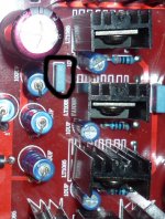
In the first version of the this board near the regulators analog power DACs has the capacitor 0.1uf. Very strange, but this capacitor has only one regulator? I can remove the capacitor, or need to add two capacitors to other regulators?
I learned how to make the ground trace a part of the board where the op-amps. There are two ground trace, one ground trace ends on the regulators LM317/337, other ground trace is only for op-amps. This is the proper organization of the ground trace?
I learned how to make the ground trace a part of the board where the op-amps. There are two ground trace, one ground trace ends on the regulators LM317/337, other ground trace is only for op-amps. This is the proper organization of the ground trace?
Attachments
Dual AK4399/ AK4118 finished
I have finished with this DAC kit, the new device earning his place into my main audio system.
I manage to implement it like follows:
- two separate mains PCB capsulated EI transformers /digital and analog were separate
- mains filter inside IEC chassis mother plug
- soft recovery rectifiers diodes on analog section PSU (BYW27/200)
- ELNA Silmic II caps for the analog PSU
- Panasonic FC for decoupling the +/_ rails of the OPAMP
- small caps around the OPAMP (part of the output filter build around OPAMP) - Siver Mica
- all decoupling caps in digital section replaced with os-con type, Panasonic SEPF series
- RCA coaxial PCB plug replaced with isolated panel BNC
- original opamps changed to LT1360 with incredible results. Results are stellar !
I have write a small post on my webpage, and few pictures regarding this project, here:
attitube: Dual AK4399 / AK4118 DAC
(I am not selling something on my website)
I am really happy with this kit the way I have finished, and I want to thank to all, but especially to nino-simona, terranigma, valeri100, kukynas, sunsun22, pinnocchio and those I don't remember for their kindness to share all their experiments in tuning/modding this little double head beast !
One should spend many more money to obtain similar results. I have tested/listened dacs with PCM1704k dual, AD1955a dual, PCM1794a and dual WM8741, and none convinced me like this AKM based kit. For a proper implemented ESS9018 (Twisted Pear, for example), one should spend at least double to get the juice out of that chip.
This kit sounds Natural and Relaxed, like Bob Marley after a recording session for the Exodus disc
Attachments
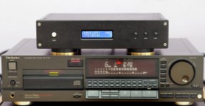
el156se: Thanks for sharing your findings with us, I enjoyed reading your blog post, congratulations with a successful project! That cd-player is nice, must be a great transport too.
magicwolf: The 100n capacitor isn't needed, it's bypassing the output cap of one of the analog +5V regulators. I think the designer forgot to draw another one for the second regulator, but they aren't needed anyway.
Your second question isn't understandable to me. In general grounding must be star type, to avoid ground loops. The opamp grounds must connect to that point, but also the grounds of the RCA sockets must connect to it with a dedicated track. Maybe you can clarify your question with a picture.
pca01: I found a way to translate the pdf. Explanation is like I thought it was the first time.
Last edited:
- Status
- This old topic is closed. If you want to reopen this topic, contact a moderator using the "Report Post" button.
- Home
- Source & Line
- Digital Line Level
- ebay:Weiliang Dual X2 AK4399 DAC with LCD