Please, report as you made this of mod.I transferred digital +5V to the other group
transferring digital +5V
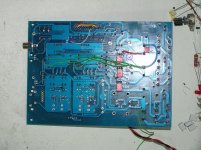
The analog and digital +5V of both dacs is supplied by the 3 regulators and share one smoothing capacitor and rectifier group. There's quite some current needed, max 90+ 90+140 = 420 mA. I decided to try and relocate the 140mA digital +5V supply and connect it to the other group, supplying the AK4113 and MCU, to decrease the loading of the group and have better performance on the important analog +5V of both dacs.
Because of an earlier experiment, I already changed the smoothing cap of the digital group to a 10.000u/25V Elna LAH capacitor. I don't think it's necessary to change if you are using 8200u Elna for audio. But I did anyway.
I had to cut the track to the input leg of the digital +5V regulator, originally connected to the same capacitor as the analog +5V regs, and attached a wire from the regulator input to the other group's capacitor (the 10.000u, red wire in the picture).
Next the bad grounding needs to be solved. This dac version 1 has the (analog) ground plane of the dacs connected directly to the (digital) ground of the AK4113 and MCU, which isn't according to datasheet recommendations. When the digital +5V of the dac has been transferred to the other group, this bad grounding will lead to distortion in left channel of the dac. To avoid this, I separated AK4113/MCU ground with dac ground plane, and connected both grounds at the supply side by connecting the - of the capacitors of both groups with each other (blue wire). You can see the rectangular ground plane of the AK4113 at the top of the picture, being cut from the bigger ground plane of the dacs.
The green (ground) wires are the main ground/return connections of the regulators, as a result of the regulator grounding mod I described earlier.
Nino
Please, report as you made this of mod.
The analog and digital +5V of both dacs is supplied by the 3 regulators and share one smoothing capacitor and rectifier group. There's quite some current needed, max 90+ 90+140 = 420 mA. I decided to try and relocate the 140mA digital +5V supply and connect it to the other group, supplying the AK4113 and MCU, to decrease the loading of the group and have better performance on the important analog +5V of both dacs.
Because of an earlier experiment, I already changed the smoothing cap of the digital group to a 10.000u/25V Elna LAH capacitor. I don't think it's necessary to change if you are using 8200u Elna for audio. But I did anyway.
I had to cut the track to the input leg of the digital +5V regulator, originally connected to the same capacitor as the analog +5V regs, and attached a wire from the regulator input to the other group's capacitor (the 10.000u, red wire in the picture).
Next the bad grounding needs to be solved. This dac version 1 has the (analog) ground plane of the dacs connected directly to the (digital) ground of the AK4113 and MCU, which isn't according to datasheet recommendations. When the digital +5V of the dac has been transferred to the other group, this bad grounding will lead to distortion in left channel of the dac. To avoid this, I separated AK4113/MCU ground with dac ground plane, and connected both grounds at the supply side by connecting the - of the capacitors of both groups with each other (blue wire). You can see the rectangular ground plane of the AK4113 at the top of the picture, being cut from the bigger ground plane of the dacs.
The green (ground) wires are the main ground/return connections of the regulators, as a result of the regulator grounding mod I described earlier.
Nino
Attachments
terranigma
Please tell me how to properly connect audiotransformation to Dual AK4399?
http://item.taobao.com/item.htm?id=38377292125&spm=2014.21088516.0.0
Please tell me how to properly connect audiotransformation to Dual AK4399?
http://item.taobao.com/item.htm?id=38377292125&spm=2014.21088516.0.0
standing on 2 Ground
2 grounds, isn't it what AKM mean in the datasheet page 35?
they name it as "Digital 5v" amd "Analog 5v". DVDD must be connected to digital ground, but VDDs and VREFs connected to analog ground.
isn't it what AKM want from pcb designer? correct me please if I'm wrong.
I hope Mr. WEILIANG's English knowledge would be much higher than me.
thanks for the wonderful job you did Nino to explain the problematic in this board.
Last edited:
terranigma
Please tell me how to properly connect audiotransformation to Dual AK4399?
µÏ±¦DB1736 ¿ÉÌæ´úLundahl LL1527µÄÒôƵÐźűäѹÆ÷ ƵÏì³öÖÚ-ÌÔ±¦Íø
Hi lomonosoff,
I tried to show two alternative connection diagram (I & II) for one channel. You can figure out other channel by yourself.
Don't forget that when you first power up the board with transformers attached, keep your two fingers in touch with AK4399 chips. In case of out of phase, wrong connection (or if dac aren't in mono mode), dac outputs see excessive load then heat up in short time which goes to chip damage.
Attachments
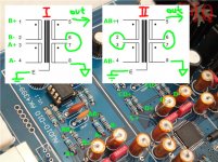
In figure 17 on page 35, you can see that also DVDD (digital +5V) is decoupled to analog ground plane of the AK4399. So for the AK4399 analog and digital supply are separated, but their currents return to the same analog ground (VSS1-VSS4).2 grounds, isn't it what AKM mean in the datasheet page 35?
they name it as "Digital 5v" amd "Analog 5v". DVDD must be connected to digital ground, but VDDs and VREFs connected to analog ground.
isn't it what AKM want from pcb designer? correct me please if I'm wrong.
I hope Mr. WEILIANG's English knowledge would be much higher than me.
thanks for the wonderful job you did Nino to explain the problematic in this board.
The design problem is just the location where the (digital) ground of the MCU / AK4113 and the AK4399 ground plane are connected. By cutting the connection as I indicated, return currents are forced to flow back the correct way, without disturbing the dacs.
terranigma: nice pic, explains clearer than 1000 words
")
terranigma: nice pic, explains clearer than 1000 words
Thanks mate..that's the best way to get through the language barrier that I suffer.
dvdd got 9.2v, do not ask how
Most probably. I came across to replacing both chips while playing with the regular of dvdd supply.
I assume you are talking about dvdd voltage of AK4399 dac chips, not the AK4133 receiver chip.
If you are confident about your soldering skills, you can replace them by yourself though desoldering part is harder than soldering new ones.There is always a risk for damaging solder footprints on board if desoldering not done properly and gently.
I used low temperature melting alloy for desoldering chips.
This is the one that I purchased & used:
9" Desoldering Alloy 158 Degree Fahrenheit Low Melting Point SMD SMT Repair | eBay
Here is the video about how use it:
https://www.youtube.com/watch?v=FTQqjggeklo
I bought chips here:
Aliexpress.com : Buy new hope XR1151 B628 SOT23 6 Boost Converter from Reliable converter usb suppliers on new hope Electronics Co., Ltd. | Alibaba Group
Here is cheaper at per item but I don't know anything about item's and seller's reliability due to low price. Consider as for your own risk.
Aliexpress.com : Buy AK4399EQP AK4399 4399 free shipping 5PCS/LOTS from Reliable Integrated Circuits suppliers on LUSKD
You can also ask electronics repair and mobile phone services at your location for replacing chips after getting new ones. I suggest you to do this first then you can try to do it for yourself if no having other option depending on your situation and skills.
But first of all make sure your chips are really gone.
Good luck.
Last edited:
Hi Luca,
Sorry for replying late. Glad you managed to solve the problem! I took a look at the pictures.
What strikes me, is that the capacitors you're using are so big. You don't need 25V caps for decoupling 5V: 6.3V types will suffice, they are much smaller in diameter.
Because the TVDD mod had so much influence on sound signature of the dac, I eventually changed the 1u polyester caps back to 100n PP, and the 100u Silmics at VREF I changed back to 47u Silmics. I like the sound better this way, the PP (Panasonic) bypasses combine great with the Silmics.
IMO the big Silmics for digital +5V are overkill, did you have better sound with bigger ones?
I did another mod to the +5V supply of this DAC, namely I transferred digital +5V to the other group, the same as which supplies +5V for MCU and 3.3V for AK4113. This way analog +5V, which needs the most current, will have it's own supply group. Impedance improves, better SQ. But you'll need to cut some tracks, I don't know you will be into this right now...
I agree, PCB isn't HQ... design either, but with some work and experiment, I have a nice sounding dac now, very rewarding in the end. Did the mods you did so far suit your needs? I hope so...
Regards
Nino
Hello, thanks for the suggestions, but i think this PCB has reached its phisical limits now, i don't think it can stand anymore change. I used 47uF caps for VREF, so no need to change.
I used those caps so big because... that's what i had at home! Their size would have been OK anyway, if only PCB pads were a bit stronger...
That's OK now, but all these mods did not better the sound as much as the voltage increase to AK4113 TVDD did: that one is a killer mod!
Maybe LT3080 regs would suit better this DAC, i used them in other projects and they're really amazing, maybe better than TI TPS.
Hello to everybody,
i managed to replace Weiliang poor XMOS using a Jlsounds I2SoverUSB board, connecting it via SPDIF instead of I2S. I used a small 2x6V transformer and a dual TPS power supply as support.
Here you can see a picture:

At first i tried to connect USB input of Jlsounds board to USB input of the DAC (using Weiliang XMOS connector), but the board is not correctly detected by my PC that way - so i had to make an hole in the rear of the DAC to allow direct USB connection to Jlsounds board. Output from Jlsounds board is via SPDIF, directly connected to Weiliang XMOS connector, so this remains an USB input that AK4113 can manage.
The resulting sound was really rich and a bit middle-bass oriented if compared to coaxial input, but that's normal as coaxial input trace has an high-pass CR filter, USB input trace doesn't (it seems to have a very small RC filter, that i bypassed).
So i implemented a small and simple CR filter (0,1 uF MKP + R 75, same as coaxial input) for the SPDIF connection from Jlsounds board to Weiliang XMOS connector, and sound opened up as coaxial sound does.
SQ this way is a bit better than coaxial input, but a bit worse than I2S connected XMOS i tested some posts ago. But it's high enough for my needs and much less complicated to manage, so i'll stay this way. ..
Just remember: straight SPDIF connection to Weiliang XMOS connector: richer and warmer sound, less controlled bass; connection via CR filter to Weiliang XMOS connector: more open sound, more "live" effect, less powerful; connection via RC filter: BLEAH!
More details and pictures here: un cinesino estremamente ben suonante - Pagina 65
i managed to replace Weiliang poor XMOS using a Jlsounds I2SoverUSB board, connecting it via SPDIF instead of I2S. I used a small 2x6V transformer and a dual TPS power supply as support.
Here you can see a picture:
At first i tried to connect USB input of Jlsounds board to USB input of the DAC (using Weiliang XMOS connector), but the board is not correctly detected by my PC that way - so i had to make an hole in the rear of the DAC to allow direct USB connection to Jlsounds board. Output from Jlsounds board is via SPDIF, directly connected to Weiliang XMOS connector, so this remains an USB input that AK4113 can manage.
The resulting sound was really rich and a bit middle-bass oriented if compared to coaxial input, but that's normal as coaxial input trace has an high-pass CR filter, USB input trace doesn't (it seems to have a very small RC filter, that i bypassed).
So i implemented a small and simple CR filter (0,1 uF MKP + R 75, same as coaxial input) for the SPDIF connection from Jlsounds board to Weiliang XMOS connector, and sound opened up as coaxial sound does.
SQ this way is a bit better than coaxial input, but a bit worse than I2S connected XMOS i tested some posts ago. But it's high enough for my needs and much less complicated to manage, so i'll stay this way. ..
Just remember: straight SPDIF connection to Weiliang XMOS connector: richer and warmer sound, less controlled bass; connection via CR filter to Weiliang XMOS connector: more open sound, more "live" effect, less powerful; connection via RC filter: BLEAH!
More details and pictures here: un cinesino estremamente ben suonante - Pagina 65
??=
I don't understand how is possible. They are both digital signal, not analogic ones!!!! Someone can explain?Just remember: straight SPDIF connection to Weiliang XMOS connector: richer and warmer sound, less controlled bass; connection via CR filter to Weiliang XMOS connector: more open sound, more "live" effect, less powerful; connection via RC filter: BLEAH!
[/URL]
I don't understand how is possible. They are both digital signal, not analogic ones!!!! Someone can explain?
It's true, we're talking about digital signal. But that's the real effect: i had another person (not into audiophility) to listen, just to be sure, and he confirmed this sound difference. In facts, that's really easy to listen: it's a neat difference.
More, if you have a look at DAC schematics, you'll clearly see what i say is true: coaxial input has a small CR circuit, and so does optical input (with different values). USB input doesn't (to be honest, it looks to me it has a small RC circuit instead, that's not depicted in the schematics).
I'm not able to explain how this works, but it does...
- Status
- This old topic is closed. If you want to reopen this topic, contact a moderator using the "Report Post" button.
- Home
- Source & Line
- Digital Line Level
- ebay:Weiliang Dual X2 AK4399 DAC with LCD