Im thinking my plan of action is going to be is to replace as you said the MIC4424/TC4424 driver IC and then, All Mosfets, output transistors and resistors just to be on the safe side.
1) Would suggest i go with higher quality mosfet piece since i compete with this amp?
2) As far as purchasing these parts...where would you suggest?
3) What do you think of what was said in this article about this amp in reference to the going from an 85*c to a 105*c for the main supply filters?
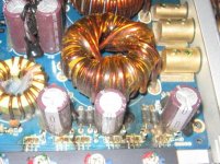
"Circuit layout is also clean. The power supply uses two main toroid transformers in its unregulated design. Of the group, Earthquake's overall efficiency was the highest.
There is no fusing, except an internal 30-amp fuse on the speaker output. Earthquake elected to use 85*C capacitors for their main supply filters. As we've pointed out in previous reviews, we feel that this is simply too low in any automotive design, and that 105*C capacitors should be used"
1) Would suggest i go with higher quality mosfet piece since i compete with this amp?
2) As far as purchasing these parts...where would you suggest?
3) What do you think of what was said in this article about this amp in reference to the going from an 85*c to a 105*c for the main supply filters?
"Circuit layout is also clean. The power supply uses two main toroid transformers in its unregulated design. Of the group, Earthquake's overall efficiency was the highest.
There is no fusing, except an internal 30-amp fuse on the speaker output. Earthquake elected to use 85*C capacitors for their main supply filters. As we've pointed out in previous reviews, we feel that this is simply too low in any automotive design, and that 105*C capacitors should be used"
You need to check the output transistors. If they're not defective, do NOT replace them.
I wouldn't use the 85c caps on the primary side of the power supply but if they didn't fail, they have been OK for many years. If you are going to replace them, I'd recommend the FC series sold by Digikey.
I'd suggest using exact replacement parts.
Digikey should have all the parts you need for the power supply.
http://search.digikey.com/scripts/DkSearch/dksus.dll?Detail&name=RFP70N06-ND
http://search.digikey.com/scripts/DkSearch/dksus.dll?Detail&name=576-1199-ND
You'll have to measure the capacitors to order the correct replacements.
yes, the ones that perrybabin states can be used but the crossreference ones i used was IRF1010 and make sure you change the TC4424cpa ic and check the gate resistors, thats just for the power section. check your output fets i think its 40N06 if there is any short, and have a 13.8 powersupply with atleast 5amp just to start up without much feedback power if there is any short that is overlooked, by the way 6 fets in the powersupply stage can juice up your output to produce sound if in any doubts.
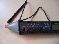
ok guys.... let me know if i did it right, i set my meter to 0.L m-(ohms) for mega-ohms
1) I checked the mosfets on the power side to see what mega-ohms readings i was getting and all of them read 0.00, (no resistance)
2)On the output side of the mosfets i get readings of 6.35 , .23 , and o.oo . What does this mean?
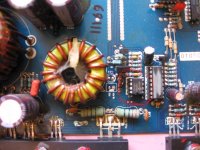
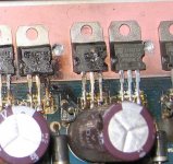
3)I could not locate the MIC4424/TC4424 driver IC and 10 ohm gate resistors but i did locate the "IC8" chip. See pic below
1) I checked the mosfets on the power side to see what mega-ohms readings i was getting and all of them read 0.00, (no resistance)
2)On the output side of the mosfets i get readings of 6.35 , .23 , and o.oo . What does this mean?
3)I could not locate the MIC4424/TC4424 driver IC and 10 ohm gate resistors but i did locate the "IC8" chip. See pic below
Attachments
Ok Mvap, lets begin here, if you are testing for those fet readings the megaohms would be too high if your tester is on a manual setting, not saying you did not get zeros on the powerfet reading, but what if the megaohm reading did not resolute to the lower ohm (in other words the reading did not reflect the tester).
Getting zeros at a lower scale is a case where the fets are destroyed. and a sign of fireworks in that area is definately no good fets.
The readings you got for your output fets sounds ok, in regards to the zero reading you got, is from the output resistor (generally 0.22ohms)p.s. there we go again base on your multimeter tester you wont get the .22 reading if your setting is too high.
The chip you have circled in the pic is definately the tc4424cpa chip which is indeed IC8, as for the gate resistors they are located near the powerfets a 10ohms color code would be :brown:black:black
Fourthly my instincts tells me you are not capable enough of fixing this amp, you could end up doing more damages, there are more complex issues that goes way beyond rocking a few fets.
Well Formas... I never claimed to be an expert at this, just a person who likes the electronics of amplifiers and wants to learn as he goes along fixing his own. I figured since this forum dealt with the Phd2 and fixing them this would be the place to learn. Just to mention I do not only use this website only, I search other sites for knowledge as well. I hope I have not aggravated anyone, it was not my intention. I just want to do it myself. So if you are inclined to lend your knowledge then, please, by all means do so. However, if you do not want to, then I completely understand. Or if there is someplace I can go that's for beginners like myself, could you point me in that direction? Anyones assistance in the matter would be greatly appreciated.
- Status
- This old topic is closed. If you want to reopen this topic, contact a moderator using the "Report Post" button.
- Home
- General Interest
- Car Audio
- Earthquake PHD2 seems to lower output???