The main idea is to make it small with superior performance
When compared to a chip (IC) audio amplifier..... or will be much more clever to assemble an Integrated Circuit if we cannot make it small.
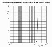
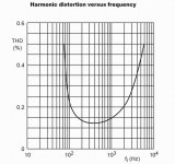
You see this one..... TDA1519.... look at the performance and distortion in the datasheet...and it is small and stereo..... if not small and better, would be more clever to build a TDA1519.
I think i will make it.
regards,
Carlos
When compared to a chip (IC) audio amplifier..... or will be much more clever to assemble an Integrated Circuit if we cannot make it small.
You see this one..... TDA1519.... look at the performance and distortion in the datasheet...and it is small and stereo..... if not small and better, would be more clever to build a TDA1519.
I think i will make it.
regards,
Carlos
Attachments
Last edited:
The board is ready...soon i will assemble
Have to ask permission to my surgeon...he said i cannot be sitted for more than 3 minutes.... also he said that is much better to avoid to sit and to be layed down in the bed in horizontal position.... i have 100 centimeters cut into the bely that can be damaged (open) if forced.
Here you have a video about the board being made:
Dx Dc prototype board ready to go! - YouTube
regards,
Carlos
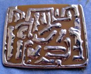
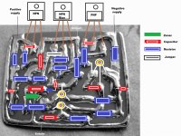
Here you see how it gonna look
It is not complete, not ready and have no values because i gonna decide the final values in the workbench.
It may have errors....but when assembling i gonna face them and will fix them...also will inform you when posting the real world assembled board.
Board artistic style is ancient Maia.... the shape reminds a stone from Machu Pichu .... Inca and Aztecs
regards,
Carlos
Attachments

Last edited:
hi Carlos, i hope all is well. i have found your project through youtube and very interested in building your project, i'm a amateur in electronics and this seems great to tinker around with.
one thing i'm not to sure on is the parts i need and if they are easy to get at a local electronics store.i'm not looking to power a huge sound system, just some Cheap(decent quality if possible) stereo speakers, i'm sure 10watts would be more than enough so 5watts each channel.
any help from you and the DIY audio forum would be greatly appreciated
thanks again")
one thing i'm not to sure on is the parts i need and if they are easy to get at a local electronics store.i'm not looking to power a huge sound system, just some Cheap(decent quality if possible) stereo speakers, i'm sure 10watts would be more than enough so 5watts each channel.
any help from you and the DIY audio forum would be greatly appreciated
thanks again
Thank you...my efforts are also to provide people like you all the help you need
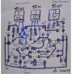
I am thinking to use darlingtons in the output, to make the amplifier simple, this way only two transistors to the input differential pair, one small transistor to VAS and two darlingtons in the output... the ones i have to make tests are TIP102 and TIP107.
I am not sure if it will result stable.... really, to be sure i have to tweak and try and to use all resources i have.... we gonna see what gonna happens.
The idea is to make it simple, small, and better in sonics than regular integrated circuits..... using discrete parts in some kind of high dense construction...the board i am showing is too much big...i am thinking it can be reduced 30 to 40 percent in its dimensions.
I do not know about other darlington transistors...... but it seems that any 30 watts darlington transistor (or more), able to dissipate 20 watts or more, that can face 40 volts from Colector to Emitter, and able to face 2A (or more) from Colector to Emitter will be good to be used... the ones dedicated to audio will be better than the ones are advertised as "switching power transistors"...these ones will work, but will be more problematic.
I will inform the transistor types as soon as i test.... BC547/557 or BC546/556 or 2N5401/5551 may be used to differential and voltage amplification stage...these ones will be tested.
I am healing from surgery...as soon as my surgeon say i can be sitted for long time i will work hard and soon you gonna have results that you can trust...and tests will be made, not only real life but also into simulator...also live tests will be recorded in audio and video.
If darlington results not good..then i gonna jump to the highly tested Dx amplifier...and then we gonna have a good amplifier anyway.
regards,
Carlos
Heatsink..... all i can do stand up i gonna do.
video attached,
Desintegrated amp - Dx Dc - the heatsink - YouTube
regards,
Carlos
video attached,
Desintegrated amp - Dx Dc - the heatsink - YouTube
regards,
Carlos
Dx Desintegrated circuit - Dx Dc - screw into heatsink
Video attached,
Desintegrated - Dx Dc - screw into heatsink - YouTube
regards,
Carlos
Video attached,
Desintegrated - Dx Dc - screw into heatsink - YouTube
regards,
Carlos
Dx Disintegrated circuit - Dx Dc - glue the board
Video attached,
Sorry, microphone was obstructed by scotch adhesive tape.
Disintegrated - Dx Dc - glue the board - YouTube
regards,
Carlos
Video attached,
Sorry, microphone was obstructed by scotch adhesive tape.
Disintegrated - Dx Dc - glue the board - YouTube
regards,
Carlos
Power darlington transistors now in place
I will try darlington...if i face stability issues, then i will make another one based into the Dx amplifier.
Here you have a video:
http://www.youtube.com/watch?v=SLfKjWb8EBY
And the transistor datasheet attached.
regards,
Carlos
I will try darlington...if i face stability issues, then i will make another one based into the Dx amplifier.
Here you have a video:
http://www.youtube.com/watch?v=SLfKjWb8EBY
And the transistor datasheet attached.
regards,
Carlos
Attachments
Last edited:
I have tested.... it is working
I have a lot to do.... was just a fast test....i will continue.
Test of Dx Dc_ the disintegrated amplifier - YouTube
regards,
Carlos
I have a lot to do.... was just a fast test....i will continue.
Test of Dx Dc_ the disintegrated amplifier - YouTube
regards,
Carlos
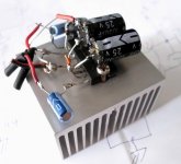
DxDc amplifier today..... the way it is today...not ready..under testing
I have already shorted two pairs or darlingtons....first was because i made a mistake and the stand by current was 400 miliamperes...this forced the amplifier to an idle power consumption (and heat of course) around 16 watts..then the small heatsink was not enough and the transistor was shorted..blew up.
There's no signal of unstability and oscilations.
The second pair i have shorted was because i have installed one transistor loosen....the screw was not tight and i have forced the amplifier for long time into distortion, the temperature arise and i have not perceived..the current increase and the thermal control was not enough to reduce it (small heatsink) and then transistor shorted.
Not only this stuff, but also i have to tune it better....i do think i would need a little bit more high end..the capacitors applied to the darlingtons seems too much big...this make it more stable but not good for high end reproduction, speed, slew rate, transient and so on (560pf)
This schematic may change a lot..not approved for a while..do not assemble...or do it under your own risk.
I repeat...not ready to go...just to show you something is progressing.
Sound is great... also power is enough (Rolls Royce)....i will make better recordings using the Kodak Playfull Ze1 camera...then you gonna perceive the audio quality....gonna do it today...not a final quality that may increase...but the way it is today.
regards,
Carlos
Attachments
Better test having a much better digital camera recording soon
One more hour and it will be ready and i gonna post it.
For a while you hasve this video:
DxDc - we gonna listen with good recording soon - YouTube
regards,
Carlos
One more hour and it will be ready and i gonna post it.
For a while you hasve this video:
DxDc - we gonna listen with good recording soon - YouTube
regards,
Carlos
Here you can listen and will be able to evaluate the quality
You can see the sound is fine:
DxDc recorded by a better camera - YouTube
regards,
Carlos
You can see the sound is fine:
DxDc recorded by a better camera - YouTube
regards,
Carlos
One more video with the DxDc recorded by a Kodak camera
This has a little bit better audio because was recorded by the Kodak Playfull Ze1.
Sadly Kodak stopped to produce... this was the last model Kodak made.
DxDc prototype live recording by camera mic - YouTube
regards,
Carlos
This has a little bit better audio because was recorded by the Kodak Playfull Ze1.
Sadly Kodak stopped to produce... this was the last model Kodak made.
DxDc prototype live recording by camera mic - YouTube
regards,
Carlos
I have made more recordings at 10 watts RMS - DxDc the amplifier used
The prototype under testing is behaving fine.
Recordings where made using Kodak, Canon and Mitsuca cameras.
DxDc - 10 watts easy with 21 plus 21 Volts supply - YouTube
If you like the stuff, then subscribe to my channel:
destroyersoueu - YouTube
regards,
Carlos
The prototype under testing is behaving fine.
Recordings where made using Kodak, Canon and Mitsuca cameras.
DxDc - 10 watts easy with 21 plus 21 Volts supply - YouTube
If you like the stuff, then subscribe to my channel:
destroyersoueu - YouTube
regards,
Carlos
Maybe.... i have made that from the scratch..... but other guys
can take the same decisions about current, voltages and parts..... i do not know about this one you are telling about....for sure i have not copy them....i am happy if they are alike....seems i have take the good decisions.
I use to do by myself..... inspired in Doctor Self circuits (book) and also some ideas from Aspen amplifiers...things my friend Hugh Dean have told me to use and the good example was the famous and wonderfull Aksa 55.
There's no original ideas in this world....thousands have learned...millions of books have been published...the internet has 10 of thousands schematics...for sure we are the result of others.
Tekko in my language is someone that is not a technician...he is a little technician...someone that learned tips and tricks alike me... so, I am a Téco...and you are a Tekko because your nick name.
This amplifier is mine... DxDc...from the scratch and sketch, was created (idea, conception), calculated (designed), assembled and tested by Destroyer x..... if someone made copy...was elector...they may have entered a time machine..then landed in this time and forum and copied the amplifier to publish in their magazine..for sure i have not readed that magazine....so...if someone have copied..they did!
Ahahahahah!
By the way .... Elecktor was published in Brasil imported from Argentine...was a hell expensive and circuits shown were filled with unobitanium (hard to find) parts..... magazine had zillions of advertisement and almost none circuit to assemble....i was not buying or reading Elecktor
regards,
Carlos
Last edited:
I have played around with a very similar circuit: http://i.imgur.com/AjAWI.png
1982 Elektor amp - YouTube
1982 Elektor amp - YouTube
- Status
- This old topic is closed. If you want to reopen this topic, contact a moderator using the "Report Post" button.
- Home
- Amplifiers
- Solid State
- Dx Disintegrated Circuit - Dx Dc