...... I'm sorry ,have found one mistake , I have corrected and below are the right files for this amplifier .....")
regards
Alex.
regards
Alex.
Attachments
Good Alex mm .... i am glad you have found something and have fixed.
Here is a video about you:
Alexandru is the great...but this pcboard is mine - YouTube
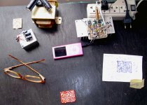
Images attached...about my board.... Dx Home board.
regards,
Carlos
Here is a video about you:
Alexandru is the great...but this pcboard is mine - YouTube
Images attached...about my board.... Dx Home board.
regards,
Carlos
Attachments
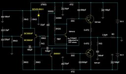
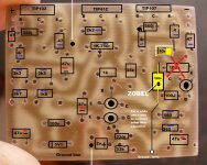
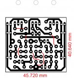
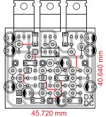
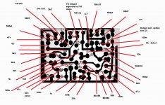
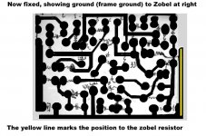
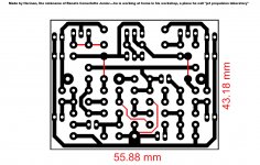
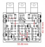
.......I'm great but only in kg 109 ,another small error TIP 41 will be change with BD139 for correct function in my previous PCB .(base inverted with emiter) not big deal .
Now, the real and correct PCB for amplifier in attachment . Zobel filter included on PCB . Carlos you are faster then me, and your amplifier will play music soon .Thanks for video . I have to wait until next weak .......
regards
Alex.
,another small error TIP 41 will be change with BD139 for correct function in my previous PCB .(base inverted with emiter) not big deal .Now, the real and correct PCB for amplifier in attachment
. Zobel filter included on PCB . Carlos you are faster then me, and your amplifier will play music soon .Thanks for video . I have to wait until next weak .......regards
Alex.
Attachments
Thanks Alex.... at least i am faster then you
Well...i have to beat you in something...what a ******* thing that you do always better boards than i do....Ahahahahahah
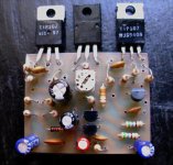
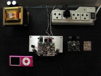
DxDc - home board edition assembled.
Will play music today!
regards,
Carlos
Well...i have to beat you in something...what a ******* thing that you do always better boards than i do....Ahahahahahah
DxDc - home board edition assembled.
Will play music today!
regards,
Carlos
Attachments
I am glad you like it Norazmi...when listening you will like it even more!
here you have a video about the zobel:
We have zobel, a wrong one but we have it - YouTube
regards,
Carlos
here you have a video about the zobel:
We have zobel, a wrong one but we have it - YouTube
regards,
Carlos
Attachments
Herman made pcboard..... he is studying and soon we gonna have final results
He use to make while we go talking and discussing details.... we have the same language and this makes communication easier.
Not final work...he is doing....on the go for a while.
regards,
Carlos
He use to make while we go talking and discussing details.... we have the same language and this makes communication easier.
Not final work...he is doing....on the go for a while.
regards,
Carlos
Attachments
Herman pcboard is not ready to go...we are studying the stuff together
Not ready....wait a little bit if you want to use Herman board..not tested too....... have a lot of jumpers and the capacitors are bigger than board (electrolitic).... this gonna be fixed..we are discussing these details.
Alex mm board was not tested also.
The only one that is being tested (for a while) is mine one.
Do yours if you want... and post it here too.
regards,
Carlos
Attachments
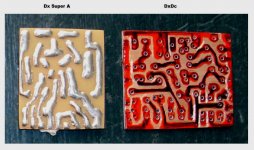
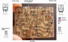
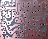
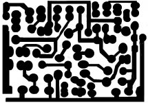
Here you have fixed home pcboards..... home ones are the hand produced
sketches to make boards home style.
regards,
Carlos
sketches to make boards home style.
regards,
Carlos
Attachments
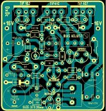
These batteries may end very fast.... i have not tested it yet
May not be approved.
I have tested the small board and worked fine:
DxDc small home board test passed - YouTube
regards,
Carlos
May not be approved.
I have tested the small board and worked fine:
DxDc small home board test passed - YouTube
regards,
Carlos
Amplifiers that lack emitter resistors are generally smoke generators too.
It might work OK with bias set to class B, the internal bias resistors will allow for the feedback loop to be completed. I would probably start out with about 2V bias between the pair of outputs (about one diode-drop less than class AB), and see how it goes from there.
It might work OK with bias set to class B, the internal bias resistors will allow for the feedback loop to be completed. I would probably start out with about 2V bias between the pair of outputs (about one diode-drop less than class AB), and see how it goes from there.
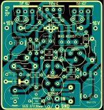
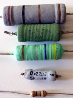
This one has emitter resistors.... 0.47 ohms.
It also uses Zobel filter and output inductor, as also Miller capacitor and RF input filter too.
You said would set to 2 volts the bias... then do it and tell me your own results...you are invited to check your thoughs and share them to our community.
I have give up to make too much thoughs...i do real life tests..they answer my doubts in a very perfect way... real world tests say to me.
- "go!".... or "not go!"
I love these words together.... "go from there".... this is the base of try and error...i love that as all i have learned was a result of that.
regards,
Carlos
Last edited:
- Status
- This old topic is closed. If you want to reopen this topic, contact a moderator using the "Report Post" button.
- Home
- Amplifiers
- Solid State
- Dx Disintegrated Circuit - Dx Dc