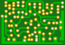
Nice Vargas...thank you very much...lovely job you have done
much appreciated dear friend Juan Vargas.
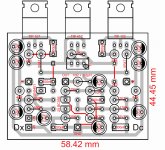
Please, put more clearance..more distance in between the copper tracks maked using white line...melted solder can spread and produce a short there.
regards,
Carlos
much appreciated dear friend Juan Vargas.
Please, put more clearance..more distance in between the copper tracks maked using white line...melted solder can spread and produce a short there.
regards,
Carlos
Attachments
Last edited:
Is all cool
 Is all cool Carlos this is a draft I appreciated that you are pointed to the tracks distance that can result in short out, I didn't realize how close they were so you did the right thing, so this means I learn from that, and it really doesn't bother me, never the less make me feel happy for it, also means more thinking good da hell yeah! remember I'm a crazy Puertorrican lol
Regards
Juan
Is all cool Carlos this is a draft I appreciated that you are pointed to the tracks distance that can result in short out, I didn't realize how close they were so you did the right thing, so this means I learn from that, and it really doesn't bother me, never the less make me feel happy for it, also means more thinking good da hell yeah! remember I'm a crazy Puertorrican lol Regards
Juan
Last edited:
Thank you very much dear Juan... we have Herman from Brasil
that is also helping us...so, we have now several options...people can buy if they want..the amplifier was tested and approved.
To 8 ohms we can use 21 to 22 volts symetrical supply
To 4 ohms we should use 16 plus 16 volts to stay in the most safe side
I have not tested the 9 volts version...will do that next week.
As you know i have assembled two different versions, all that published.
We have now several options of boards, people can make their choice.
Mine own pcbboard style and my pcboard modern style
Alex mm pcboard
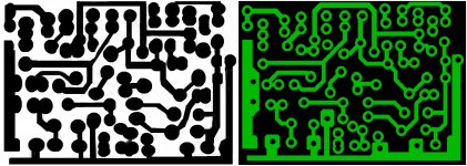
Juan Vargas pcboard
Herman pcboard
More videos to come with more instructions and the amplifier description will be made.
Herman boards will be attached to this post.
regards,
Carlos
that is also helping us...so, we have now several options...people can buy if they want..the amplifier was tested and approved.
To 8 ohms we can use 21 to 22 volts symetrical supply
To 4 ohms we should use 16 plus 16 volts to stay in the most safe side
I have not tested the 9 volts version...will do that next week.
As you know i have assembled two different versions, all that published.
We have now several options of boards, people can make their choice.
Mine own pcbboard style and my pcboard modern style
Alex mm pcboard
Juan Vargas pcboard
Herman pcboard
More videos to come with more instructions and the amplifier description will be made.
Herman boards will be attached to this post.
regards,
Carlos
Attachments
I like his style, also your style, i do appreciate Alex mm style and i do love mine
style too...they are all fine.
Several options...and people can also build their own style.
My duty is to give them all the options, informations, papers, videos and to answer their questions and help them to assemble.... what they gonna make and how they gonna make it is up to them.
regards,
Carlos
DxDc schematic attached
R7 is the gain resistor....reduction of the value will increase sensitivity...i am using 1K to the MP4 player..... naturally, the increase in its value will decrease sensitivity....more milivolts in the input will be needed in the second case to drive the amplifier to full power.
regards,
Carlos
R7 is the gain resistor....reduction of the value will increase sensitivity...i am using 1K to the MP4 player..... naturally, the increase in its value will decrease sensitivity....more milivolts in the input will be needed in the second case to drive the amplifier to full power.
regards,
Carlos
Attachments
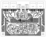
Example of my favorites layouts Alex MM and Nabuco
Is true Carlos I personally like Alex MM style of layouts and yours too and is really interesting different styles of layout displacements make it a challenge standing up resistors, custom silkscreen resistors capacitors, now Herman style wow bro! but with all respect to mister Alex MM I have this but only for my studies don't worry mister Alex MM your are the man also mister Nabuco.
Regards
Juan
Attachments
Last edited:
They are both very good.
I do think it is better this way...not to have an official Dx Corporation layout designer... the result is several different styles...this way people can choose.
Miguel Nabuco (Mitchel) is Brazlian and from the same town i have born.... there we have strong influences from French invaders....our culture and tastes are not too much different.... french does not scream when talk, do not talk loud...as also Englishman are polite.... we do not like noise and big outdoors...in our boards we love small letters, all letters same size...something sleek and discreet....because of that i had perfect tunning with Mitchel and i do think he made perfect boards to my taste.
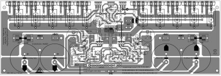
I have other great guy....Renato Comerllate Junior from São Paulo - Brazil, that is also tunned with the style of discreet, elegant pcboards .... attached one example of the old Dx Turbo he is preparing to us.... the best layout i have ever seen is this one.
regards,
Carlos
I do think it is better this way...not to have an official Dx Corporation layout designer... the result is several different styles...this way people can choose.
Miguel Nabuco (Mitchel) is Brazlian and from the same town i have born.... there we have strong influences from French invaders....our culture and tastes are not too much different.... french does not scream when talk, do not talk loud...as also Englishman are polite.... we do not like noise and big outdoors...in our boards we love small letters, all letters same size...something sleek and discreet....because of that i had perfect tunning with Mitchel and i do think he made perfect boards to my taste.
I have other great guy....Renato Comerllate Junior from São Paulo - Brazil, that is also tunned with the style of discreet, elegant pcboards .... attached one example of the old Dx Turbo he is preparing to us.... the best layout i have ever seen is this one.
regards,
Carlos
Attachments
Last edited:
Boys, you have the "go" for this project
Was deeply tested.
Survived...but some details must be said..... keep iddle current very low because the transistor used in the output are not really strong as datasheet said..they overheat because the metal back is too much small...say...the metal that goes in contact with the heatsink is too much small.... this does not allow heat transference to the heatsink.
If you have not experience this in your life and mind, then try to heat a heatsink using the soldering iron tip... put it vertical, only one square milimeter of the tip (small contact area) touching the heatsink...you will see that you will not increase the heatsink temperature....now try to touch it horizontally and melt some solder around the big tip that will touch the heatsink...now you will perceive the heatsink as hot.... bigger area means better heat transference.
This way, to 8 ohms you can use till 22 volts Dc supplies....but to 4 ohms it is better to use maximum of 16 plus 16 volts supplies..... this is because the transistor back...too much small..too much bad to the TIP102/107....you can try TIP105 and complementary, these ones are better related it's back side, the metal case.
Keep the current low.... measure 1 milivolt above the power emitter resistors (0.47 ohms) and check if it remains more or less unchanged when the amplifier reach operational temperature (40 degrées celsius)... if the increase in current is small...or if you have some decrease....then it is fine....if not, then increase your heatsink size.
regards,
Carlos
Attachments

- Status
- This old topic is closed. If you want to reopen this topic, contact a moderator using the "Report Post" button.
- Home
- Amplifiers
- Solid State
- Dx Disintegrated Circuit - Dx Dc