Here in Australia there is a company called Conrad Heatsinks that make beautiful cast aluminium heatsinks. I used one for my Rod Elliott P3A amplifier. I doubt you will be able to find such nice heatsinks anywhere else in the world!
Heatsinks Heat Sinks Conrad Heatsinks
Heatsinks Heat Sinks Conrad Heatsinks
This looks good... i like it....but, we are not using double side pcboards
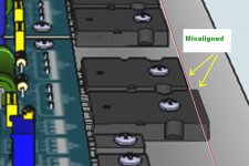
you have to solder below the pcboard....so...you have to align the leads to do it.... often these lead's high become misaligned...or small the distance or big the distance..then when you attach the pcboard support, stand or feet, you will force and detach the copper tracks.
The way you have is to put power transistor without solder it..and then attach the pcboard to the heatsink and also the power transistors...now..aligned..you twist the power transistor leads, inserted from below and appearing in the top as an excess of leads to be cutted out..... then you twist it in 90 degrees to have a reference to dismount the whole stuff and solder.
You see.... the problem is to solder when we cannot introduce soldering iron below the pcboard...maybe hot air or other method must be used.
Yes, you can use transistor dimensions as reference touching it below the pcboard..and soldering this way...but board feet (spacers) must be precise or you will force the copper to detach...if you solder transistor first and attach the whole thing to the heatsink you will face troubles....if you do not solder transistor you also gonna face problems.
Well... hard to explain using words when my native language is not the english...maybe i will have to make a video to explaiin what i mean IF you face troubles to understand me...please..let me know if you understood the trouble and if you have some clever solution...i really do not have the clever solution.
the problem is that you cannot solder power transistors before you fix the pcboard to the heatsink..because they gonna be misaligned...also you cannot left unsoldered...this is the problem.
regards,
Carlos
Attachments
Last edited:
...
You see.... the problem is to solder when we cannot introduce soldering iron below the pcboard...maybe hot air or other method must be used.
...
Well... hard to explain using words when my native language is not the english...maybe i will have to make a video to explaiin what i mean IF you face troubles to understand me...please..let me know if you understood the trouble and if you have some clever solution...i really do not have the clever solution.
the problem is that you cannot solder power transistors before you fix the pcboard to the heatsink..because they gonna be misaligned...also you cannot left unsoldered...this is the problem.
regards,
Carlos
Hello Carlos,
Suggestions:
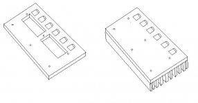
1. Make a piece of aluminum plate (6mm or so), drilled with the same mounting pattern with a cutout area for access to the transistor soldering area. Solder in place and then transfer to heat sink. (You could also use this for troubleshooting)
2. Mount the parts in place and glue the transistor leads that stick up through the top side of the board. Then when they are fixed in place, remove and solder, then remount.
")
It is already a good idea Dug
Not so easy to make it.....but if no one else come with an easier way to implement idea..then yours will be the one.
Thank you very much Doug... this demands Spatial inteligence.... space analisis...i am not that good in this stuff, so i thank you very much as the solution overloaded my old neuroniuns
"L" shape is a much better idea....easier....cleaner and almost perfect in my point of view..... but does not work for high power amplifiers because the heat transference resistance in between the "L" plate and the main heatsink.
Amplifier that pumps out 50 watts can use it if the L vertical line is big, flat and uses a huge ammount of thermal grease and also 5 screws to attach the adaptor to the main heatsink...but for 100 watts this is not working fine....and this amplifier can pump out 300 watts distorted if your supply can feed all that power...so...i have asked my layout designers to cut out (remove) the pcboard excess used as a support to the "L" bracket.
Was a standard way to use "L" shape adaptors..but MKII and also MKIII people faced troubles, because of that i suggest people to saw the pcboard r to install power transistor direct into the heatsink using wires...ugly but more effective solution.
regards,
Carlos
Attachments

Last edited:
Not sure if you misunderstood me or I am misunderstanding your reply.
By plate I meant substitute plate for soldering only.
Picture is worth lots of words.
(or at least a drawing in MS paint is)
Should not be too hard to make...same drilling pattern as heatsink.
By plate I meant substitute plate for soldering only.
Picture is worth lots of words.
(or at least a drawing in MS paint is)
Should not be too hard to make...same drilling pattern as heatsink.
Attachments
Yes...i got what you meant..... it is good
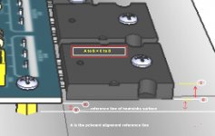
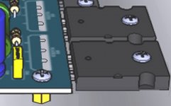
But i was thinking to put transistor below the pcboard..this way the transistor case gonna be the reference for the spacers we use to attach the pcboard into the heatsink...the yellow ones connected to the screw.
See the image...transistor goes inserted below the pcboard..this way you can solder then we cut the feet, the support, the tube that supports the pcboard and receive the screw inside, the same length as the the transistor high.
Got it?.... man.... i have no words....my english is really poor.
regards,
Carlos
Attachments
Pictures explain very well.
I have done something similar, but not quite that close.
Idea:
On that edge of the board, don't use standoffs. Just let the transistors support the board.
Then there will not be a conflict in height.
You will still have to clamp the transistors to something to get them aligned. This will be more critical now that they don't have the lead flex that they did before.
IMHO I would not do this.
Added: I also had the luxury of through plated holes...very easy to solder from the top.
Last edited:
I usually mock up the whole setup without soldering power transistors,
just bend legs to fit them perfectly.
legs end up with z bend, first 90 deg forward, then once i got distance, bend flat onto pcb surface.
Then remove pcb from heatsink with power transistors and solder power transistors with pcb removed from heatsink, but perfect bends so they fit right.
Now with power transistors soldered to pcb, I now put heatsink paste and insulators below transistors and fix them to heatsink, after that i just tighten screws to hold pcb to stand-offs.
Regards
Yep... this method works good too...i use to bend
the same way you do.... we have to adjust a little after soldering..but works fine...but if we do mistakes..then the copper track will detach from the fiberglass.
Same way Vostro...this is what i use to do....but not so perfect... sometimes if fails in my home.
I will use the transistor below and will not use supporting feet...it gonna be lift by the transistor leads...maybe a rubber glued to help to stabilize the pcboard.... one single rubber support inserted into the screw hole and below the pcboard...this is what i gonna do myself.... but now, becasue your suggestions.... yours and from Dug, people has more ideas to decide...this helps a lot...thank you very much Vostro..even in the other side of the fence you helped a lot.
Vostro is yours in Italian...nice nick name.
regards,
Carlos
Last edited:
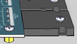
If i understood correctly..this is the way Vostro suggest
This way is good..but sometimes you have to adjust bending the transistor...leads must be long to allow you to adjust..also you must insert the same length not to have transistors misaligned.
regards,
Carlos
This way is good..but sometimes you have to adjust bending the transistor...leads must be long to allow you to adjust..also you must insert the same length not to have transistors misaligned.
regards,
Carlos
Attachments
Being a carpenter, I suggest a simple piece of wood similar to what DUG posted. If you have a saw it would be very simple to make and you just screw everything in place. Even 1/4" masonite would work. Just make the bends on all the devices and slip them through the holes in the PCB. Then screw down the PCB through your stand-offs, aligh the devices and screw them down. Flip it over and solder. Unscrew all of it from the wood, place on heat sink and mark for mounting holes. Should work great. Gonna make me one.
Not to worry about that Carlos. I love to share pics. I'm just wondering what kind of heat sink is required for the big transistors on the power supply. I haven't seen any pics of the power supply in action. You have suggested that many units have been built in Brazil. Do you have any pics of how folks have done there PSU's? I'm still awaiting parts so have some time to look for heat sinks if I need them.
Thanks, Terry
Thanks, Terry
Hello guys
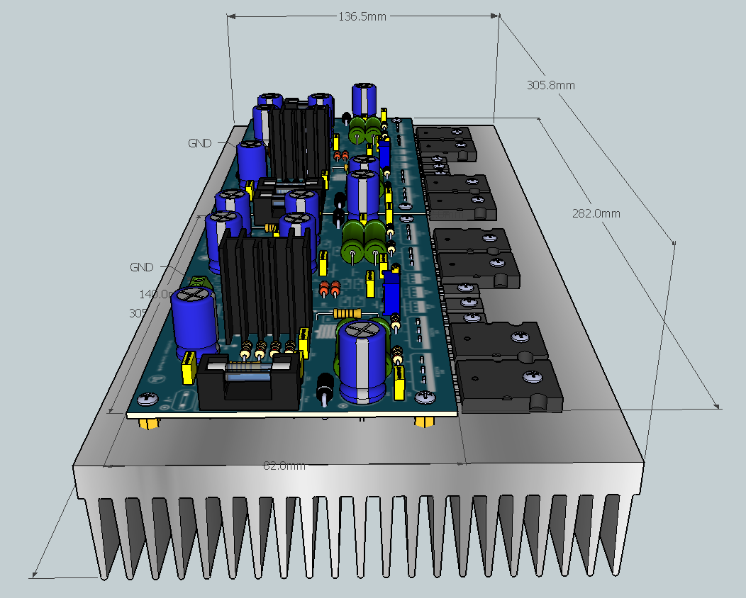
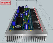
I was comparing my simulation to the real thing it was almost as I thought how will look like and I feel really happy with the results, (...)
Regards
Juan
Hi, Juan. Are you using DesignSpark?
Sorry Terry, i do not have pictures....or i have very few of them
I will ask Zimmer to send me some from builders.
Usually they make pictures using cell phones..then i do not keep the pictures because no good to be published because of quality.
I will see if i can manage to find something in good shape.
I have some from my own prototypes...but i was testing performance with several loads...some are overkill, others worked very hot... the one with wooden base (MDF) is the one faced heavy duty.
Maybe in the Dx Supply thread you will find something...have you watched there?
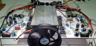
Here you have one that i have saved.... a rarity, because cell phone...very bad picture...you can see at the bottom the aluminum in U shape.
These boards are the first batch made to Brazil...the new ones are different and better compared to these ones you see..... even Juan has two models..one with transistors to use "L" shape adapter and other without the "L" shape adaptor
regards,
Carlos
I will ask Zimmer to send me some from builders.
Usually they make pictures using cell phones..then i do not keep the pictures because no good to be published because of quality.
I will see if i can manage to find something in good shape.
I have some from my own prototypes...but i was testing performance with several loads...some are overkill, others worked very hot... the one with wooden base (MDF) is the one faced heavy duty.
Maybe in the Dx Supply thread you will find something...have you watched there?
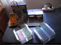
Here you have one that i have saved.... a rarity, because cell phone...very bad picture...you can see at the bottom the aluminum in U shape.
These boards are the first batch made to Brazil...the new ones are different and better compared to these ones you see..... even Juan has two models..one with transistors to use "L" shape adapter and other without the "L" shape adaptor
regards,
Carlos
Attachments
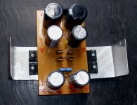
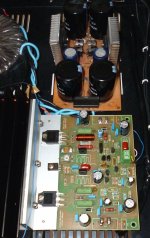
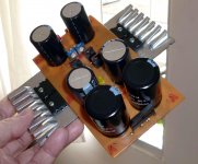
Here i have some...but all mine...prototypes tested
The Dx Supply was changed..evoluted.... at the first moment it was for 8 and 4 ohms only...and then was increased in capacity to face two channels at 8, 4 and 2 ohms...so...you gonna see several different sizes of aluminum Blade or heatsinks.
regards,
Carlos
The Dx Supply was changed..evoluted.... at the first moment it was for 8 and 4 ohms only...and then was increased in capacity to face two channels at 8, 4 and 2 ohms...so...you gonna see several different sizes of aluminum Blade or heatsinks.
regards,
Carlos
Attachments
- Home
- Amplifiers
- Solid State
- Dx Blame ST together Dx Super A