I am fine, thank you.
Less 36 kilos...more healthy, sleeping better, eating less and a more balanced and healthy food, a lot of fruits and yogurt, also some meat...i can eat everything..from 3 to 3 hours i have to eat a little.
I am rid from the Brazilian forum...also not working too much here..only doing things that gives me pleasure.... also pleasure is something i am having more frequently because of thd surgery made.
A Brazilian tried to arrest me inside a new forum but i jumped out...i runned out from the prison and responsability.
Well... dancing...living life in harmony, having fun, enjoying music, producing pictures and movies, sleeping a lot, watching a lot of satelite television...i am having a very good life.
Thank you,
regards,
Carlos
You know workhorse, you are one of the best engineers we have
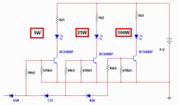
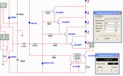
your designs are really great and superior to the most high level designs i use to see..... i would like to have this meter with a different behavior...if you know, please offer us a design or some circuit clue to me to develop.
Something that.... when reaching the threshold, let's say 10 watts RMS, then a burst of ligth and after that the led goes off .... this way only small burst of ligth when reaching the threshold... half second pulse of ligth and then going off...this may produce a nice effect.
You know...not ligth and hold...but ligth and release.... can use other circuits.... maybe a flip flop...astable or bi stable multivibrator.l
regards,
Carlos
Last edited:
your designs are really great and superior to the most high level designs i use to see..... i would like to have this meter with a different behavior...if you know, please offer us a design or some circuit clue to me to develop.
Something that.... when reaching the threshold, let's say 10 watts RMS, then a burst of ligth and after that the led goes off .... this way only small burst of ligth when reaching the threshold... half second pulse of ligth and then going off...this may produce a nice effect.
You know...not ligth and hold...but ligth and release.... can use other circuits.... maybe a flip flop...astable or bi stable multivibrator.l
regards,
Carlos
Configure a lm393 comparator for giving you Lo output every time the voltage swing rises above for 10wrms in to given load, lets say 6.3Vrms into 4 ohms makes 10wrms, this will do and the output of comparator goes to trigger pin of 555 timer into astable MV mode and connect the output to LED.
Cheers
Kanwar
I think that Carlos wanted to build a circuit powered directly from the amplifier output, which is more practical.
If it was to make a circuit with external supply, I would use the LM3915 or LM33916 - you can set for dot mode (the Led will light and release) or bar mode (led will ligt and hold).
http://www.youtube.com/watch?v=7gk_-_FpwgU
Works very nice
If it was to make a circuit with external supply, I would use the LM3915 or LM33916 - you can set for dot mode (the Led will light and release) or bar mode (led will ligt and hold).
http://www.youtube.com/watch?v=7gk_-_FpwgU
Works very nice
Last edited:
Oh yes!.... Mitchel got the point..but i asked to workhorse
Something more sophisticated...then he came with the chip.
We have already several chip options...i want that discrete... and not powered...in a such way we can use portable and measure everywhere, also to install inside a speaker without batteries or power supplies.
Using supply...well.... better to use a dedicated chip...and this is what i am trying to avoid and Mitchel got it....without supply is the main idea.
Ostry circuit is nice too..i have adapted and seems worked fine......i may try it not using a supply to see what happens.... this battery is the problem.... we can do these things without battery sockets or power cord, without transformer and all stuff.
regards,
Carlos
Attachments
Roly3055.... looks good this one..thank you very much
Nosotros, brasileños gustamos mucho de los cubanos....we.... Brazilians..we much appreciate Cuban culture.
Long time passed when i had these Tesla capacitors in my home... from the sixties...lovely ones ...was good to watch them.
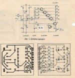
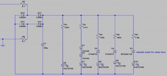
I will simulate...i really like the style...all transistors...simple circuit...the way i like...but seems to make Q5 operate we should use Germanium transistors...as 33 ohms will not develop voltage to switch Q5 on....nice.... really nice.
Thank you,
regards,
Carlos
Nosotros, brasileños gustamos mucho de los cubanos....we.... Brazilians..we much appreciate Cuban culture.
Long time passed when i had these Tesla capacitors in my home... from the sixties...lovely ones ...was good to watch them.
I will simulate...i really like the style...all transistors...simple circuit...the way i like...but seems to make Q5 operate we should use Germanium transistors...as 33 ohms will not develop voltage to switch Q5 on....nice.... really nice.
Thank you,
regards,
Carlos
Last edited:
Igualmnete los cubanos queremos mucho a Brasil, su musica, su cultura, las telenovelas brasileras son las preferidas por aca y sus mujeres muy bonitas.
Voy a revisar en la casa para ver si encuentro un esquema similar al posteado pero que venia en un blaffle Ruso Radioteknika
Voy a revisar en la casa para ver si encuentro un esquema similar al posteado pero que venia en un blaffle Ruso Radioteknika
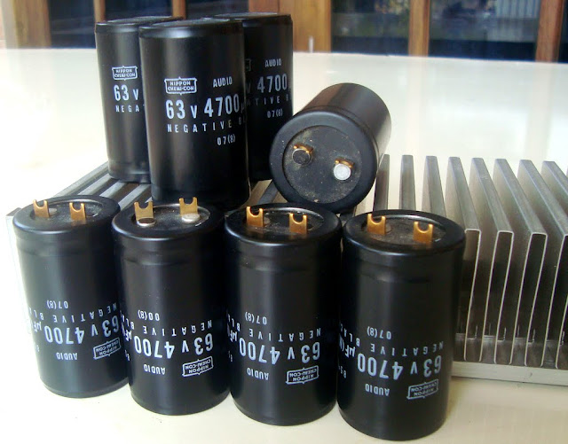
Dx Blame ST, Dx Blame ES uses 5000uf to each ampere
They are a 2.5 amperes per rail power amplifier...so, to each channel we need minimum of 12.500uf plus 12.500uf not to listen noises from the mains when you overdrive your power amplifier... this is to 4 ohms loads.
If you will operate your amplifier in 8 ohms... this way you need half of that to each channel.... 6800uf plus 6800uf will be enougth to ONE channel.
If your supply will go to feed both channels....then to 8 ohms, that single supply must offer you 12.500 plus 12.500uf and this will feed both amplifiers... current will be 2.5 plus 2.5A drained from the supply...around 1.25A plus 1.25A to each power amplifier (rail fuses).
If your supply will go to feed both channels... then to 4 ohms speakers, you will need twice the above explanation... 25000uf plus 25000uf condensers to face the huge current of 5 plus 5 amperes... each power amplifier will drain 2.5A to each rail (rail fuses, do not forget them).... the output current will be combined.... 5 ampere fuse must be inserted in series with the output line to protect speakers.... 4 amperes is a good idea too if you have weak speakers.
Each channel in 4 ohms, as i have said, will drain 2.5 plus 2.5 amperes... and each channel will send 5 amperes to the speaker
Each channel in 8 ohms, as i have said, will drain 1.25 plus 1.25 amperes, and each channel will send 2.5 amperes to the speaker
The power consumption to 50 watts of audio is around 85 watts
The power consumption to 100 watts of audio is around 160 watts
A stereo in 8 ohms will drain 160 to 170 watts from the mains..so, primary fuse to a single transformer feeding both channel will be 1.5A to 110V and 0.8A to 220V.
A stereo in 8 ohms, using one transformer to each channel, will need a primary fuse to this transformer in a value 0.8A to 110V and 0.4A to 220V
A stereo em 4 ohms will drain 340 watts from the mains..so, primary fuse to a single transformer feeding both channels will be 3A to 110V and 1.5A to 220V
A stereo amplifier operating 4 ohms will drain 340 watts from the mains (total..as each channel will drain around 170 watts), if you decide to use one transformer feeding each channel, so, two transformers inside the same enclosure, then you should use primary fuse of 1.5A to 110V and 0.8A to 220V
Bridge rectifier must be twice the total current you will have to the speakers, so, speaker fuse to each channel added one to the other will be the reference of current..multiply by two and then you have your bridge rectifier current.... of course if you decide to use two rectifier and two banks of condensers..then each one of these bridges must be twice the current (fuses) you have in series with your speakers.
You can increase these values, but please do not decrease them and do not exceed twice the values suggested because in some cases may result more problem than a good solution.
regards,
Carlos
Last edited:
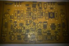
50w Power/volt meter
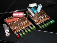
Here is my 50w version of Carlos's original design. Enjoy")
YouTube - 50w meter
Regards
Niss_man
Here is my 50w version of Carlos's original design. Enjoy
YouTube - 50w meter
Regards
Niss_man
Just made to this design. A copy of yours but for 50w power. At 1w power the 1st led lights up. Only ever so slightly. Will mount it in a box to show people what small power level is needed to make a large volume of noise/music.
YouTube - 50w meter
Regards
Niss_man
YouTube - 50w meter
Regards
Niss_man
Attachments
- Status
- This old topic is closed. If you want to reopen this topic, contact a moderator using the "Report Post" button.
- Home
- Amplifiers
- Solid State
- Dx Blame ST - Builder's thread - post pictures, reviews and comments here please.