SNG001 have assemble the Dx Blame ST...he said sound was good
I will look forward for a more detailed review about.
some pictures from him...modified because already posted..will make them different.
regards,
Carlos
I will look forward for a more detailed review about.
some pictures from him...modified because already posted..will make them different.
regards,
Carlos
Attachments
Last edited:
BlameST with Zharmo's layout
Zharmo,
I am happy to inform you that your Blame-ST layout (the one with the TO-220 drivers) had been verified.
I need a mono-amplifier to power my twenty-years old Magnat speaker in my study and I don't want to spend too much money.
Looking thru my parts bin, I found that I have most of parts for BlameST. I modified Zharmo's Blame-ST layout so that I can fit the monster DC blocking capacitor (C1).
The BlameST sounds very good and it is smooth & relaxing. The amp is quiet (no hum, no hiss) and the DC offset is 15mV.
KiCad is very easy to use. I made the following changes because I have these parts in my parts bin:
C1 : 10uF Evox film capacitor (it is huge : 30 x 23 x 13 mm)
C20, C22 : 1000uF, 63V
C14, C16, C10(bootstrap) : 100uF, 63V
C18: 270nF polyester capacitor (mounted under the board)
R3: 10R (I prefer a virtual ground for input)
R32: replaced by a link
R26 & R27 : Dual 0R22 in a single package (salvaged from a old AV amp)
- Stanley
Yes, I cannot guarantee my boards style too. i just build what i wanted.
Zharmo,
I am happy to inform you that your Blame-ST layout (the one with the TO-220 drivers) had been verified.
I need a mono-amplifier to power my twenty-years old Magnat speaker in my study and I don't want to spend too much money.
Looking thru my parts bin, I found that I have most of parts for BlameST. I modified Zharmo's Blame-ST layout so that I can fit the monster DC blocking capacitor (C1).
The BlameST sounds very good and it is smooth & relaxing. The amp is quiet (no hum, no hiss) and the DC offset is 15mV.
KiCad is very easy to use. I made the following changes because I have these parts in my parts bin:
C1 : 10uF Evox film capacitor (it is huge : 30 x 23 x 13 mm)
C20, C22 : 1000uF, 63V
C14, C16, C10(bootstrap) : 100uF, 63V
C18: 270nF polyester capacitor (mounted under the board)
R3: 10R (I prefer a virtual ground for input)
R32: replaced by a link
R26 & R27 : Dual 0R22 in a single package (salvaged from a old AV amp)
- Stanley
Attachments
Director X, guys
Agenda for extraordinary DX Corp. meeting:
1) to appoint new DX board designer
2) plan aftermarket support for ES builders
You know, Zharmo's 3D view and PCB look pretty good for this type of DIY.
Maybe someone else would like to donate their talent for the (shorter) time it might take in the future?
regards
Last edited:
KiCad file for my version of Blame-ST
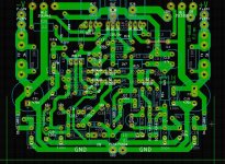
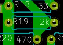
Thanks to Zharmo, who has done the hard work in putting together the schematic & the board layout. I had made minor modifications to his layout so that it will fit the Fubata MPC722 dual metal-plate resistor (R26+R27) & big input capacitor (C1) with lead spacing between 12.5 & 27.5mm.
I have attached a screenshot from KiCad & my version of KiCad files. I had build a Blame-ST successfully using these files and I made some minor changes so that the trimpot has better clearance.
KiCad is open-sourced and it is FREE and it also can output gerber files so it is good for professional board production. You have to check all the drill holes for size & grid spacing before you send the drill file off.
- Stanley
Attachments
Zharmo boards and also sng001 modifications are fine
To the Dx Blame ST, we have already a good board layout...of course to order we need Gerber files.... well, order is fine, but etch at your home is even a better DIY behavior... Todd Johnson board is good to etch at home too.
I am happy with Todd's Layout, also very satisfied with Zharmo layout.
I gonna need, something to the Troyan amplifier....this one to be released in July, Sakis have started to make a board to be tested.
To this next one, the "demolition machine", cooperation is needed, i hope Sakis manage to have time to do..but for sure he has not too much free time to do this enterprise... this gonna represent a sacrifice to him.
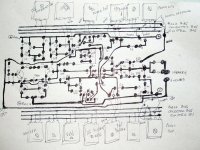
I use to offer, as a tradition, a sketch, something from my own....not pretty... exactly to show folks that i really need help, that people has some intimate relation with layout software may do it better.
I am addicted to build amplifier... i don't care how they look but how they sound.... but, for sure, good looking is attractive to builders..and these ones are my main target, to reach them, to have happy people enjoying my amplifiers the same way i enjoy..to share..to be a part of a group where we all share the same sonics, the same experiences.
I could see, observing our friend's behavior these last years, the ones loves software, to make layout, sometimes does not like to assemble... also the opposite happens..the ones loves to assemble does not love software to make layout....a more complete guy was Alex mm...but seems he is busy... Alex used to build all circuit he produced layout.... Todd has never built...he said had not time.
Zharmo did it..the complete job..created the board and have built and tested the board... this avoids surprises, as sometimes long lines in parallel, or small distance between copper lines, output coil too much close to input and several others decision mistakes can drive amplifiers to oscilation..so... this should be tested in advance to the release.
Kicad seems to be very good..the software image resolution is awsome (not the image posted).
regards,
Carlos
To the Dx Blame ST, we have already a good board layout...of course to order we need Gerber files.... well, order is fine, but etch at your home is even a better DIY behavior... Todd Johnson board is good to etch at home too.
I am happy with Todd's Layout, also very satisfied with Zharmo layout.
I gonna need, something to the Troyan amplifier....this one to be released in July, Sakis have started to make a board to be tested.
To this next one, the "demolition machine", cooperation is needed, i hope Sakis manage to have time to do..but for sure he has not too much free time to do this enterprise... this gonna represent a sacrifice to him.
I use to offer, as a tradition, a sketch, something from my own....not pretty... exactly to show folks that i really need help, that people has some intimate relation with layout software may do it better.
I am addicted to build amplifier... i don't care how they look but how they sound.... but, for sure, good looking is attractive to builders..and these ones are my main target, to reach them, to have happy people enjoying my amplifiers the same way i enjoy..to share..to be a part of a group where we all share the same sonics, the same experiences.
I could see, observing our friend's behavior these last years, the ones loves software, to make layout, sometimes does not like to assemble... also the opposite happens..the ones loves to assemble does not love software to make layout....a more complete guy was Alex mm...but seems he is busy... Alex used to build all circuit he produced layout.... Todd has never built...he said had not time.
Zharmo did it..the complete job..created the board and have built and tested the board... this avoids surprises, as sometimes long lines in parallel, or small distance between copper lines, output coil too much close to input and several others decision mistakes can drive amplifiers to oscilation..so... this should be tested in advance to the release.
Kicad seems to be very good..the software image resolution is awsome (not the image posted).
regards,
Carlos
Attachments
Last edited:
Dear Carlos, right now I am soldering the components, and I found what could be probably a hoax. Could you please explain me what is the actual value for C18? In the schematics the figure is 220nF, but in the BoM appears 2,2uF. Now I got confused about this figure. Thanks for helping me...
The amplifier was tested, several times and playing at my home
") You gonna have smoke if you light a cigar while powering it on...or if you brain burns because overdrive.
You gonna have smoke if you light a cigar while powering it on...or if you brain burns because overdrive.
ahahahahah!
Capacitor there can be 220n or 270n... this ones is "charge suckout", works only during crossover moments and while clipping.
bye Max
Carlos
You gonna have smoke if you light a cigar while powering it on...or if you brain burns because overdrive.ahahahahah!
Capacitor there can be 220n or 270n... this ones is "charge suckout", works only during crossover moments and while clipping.
bye Max
Carlos
Last edited:
It seems that Stanley´s board shows some resistors with some extra power dissipation than figured in the BoM.pdf list. Maybe 0.25W be a too low spec for them! Well, when my prototype gets finished I will feel the heat! Or watch the smoke!!!!!
Max.
Max,
I installed bigger carbon-film 1W resistor for the following reasons:
R3 (10R) - BOM requires 0.5W & my metal film resistor is only 0.25W.
R17 & R22 (33R) - these are the rail resistors, 0.25W can carry 7mA safely, so I went for for 1W.
R26 & R27 (2R2) - I only had these 1W resistors in my parts bin.
R24 (220R) - it was not listed in the v1.5b BOM, there are space for bigger resistor so I went for 1W.
The Blame-ST runs very cool, no hot spot.
- Stanley
Thanks Stanley for crystal clarifying everything!
And forgive me for the English, that is not my native language, neither the second, nor the third one! Unfortunately, here in Brazil we need to learn English or any other language by our own efforts!
I feel very happy to be understood and your words sounded like what I was expecting to hear (read!).
As soon as my homemade version of the so famous DX Blame ST gets up and running (and I'm sure it will be a great pleasure for us all), I will post the news. And, maybe, some photos, if permitted.
As time goes by.... I think things will be clear for everyone and eventually I will be able to help too, not only post questions, questions and more questions!
Thanks for the kind words.
Best regards.
Max.
I will be happy with your pictures, as i knew you are producing using the real DIY
The spirit..... alike me, you gonna be one more rarity... now a days people order from factories or etch using photographic/chemical method.... old style was almost abandoned...some few guys still uses.
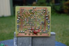
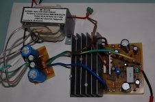
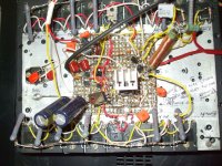
Mine boards, sometimes are point to point... a big mess.
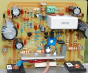
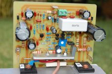
Do you know what i think?.... if an amplifier operates this way, without oscilations, we do not need to worry too much about board layout...because the amplifier proved to be stable...not oscilating after this kind of terrible construction, will not oscilate when assembled in a decent board.
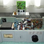
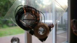
The one resulted better in sonics was this blue/gray one you see at your left... the schematic is old, from the Dx Blame ES.... having a lot of capacitors that use to slow down the circuit and result the ugliest think i have ever done...absolutelly awfull...but it is beating decent boards...not good to see...excelent to listen too...i had not courage to dismount the mess... supply is not decent too... transformer has huge voltage drop...even this way..the best unit i have .... and i have several Dx Blame ES and ST at my home.... parts selection counts too.... they sound a little bit different..even the two ones using the same board (some small differences matters)
These constructions were made by a man...the ones have not that brigth in the eyes.... macho style...no pink shoes, no hair styling emulsion...no perfum...no nail polish, no batton, no solar filter, not shaved. a male working...had sweat smell....a man you know..the one has strong voice and knowledge how to catch a woman going straigth to the point, not letting room to any doubt about his intentions (to attack and dominate)..... masculine style... without worries if pretty or handsome.... this is what means our board style, honoring the 100 women we had in this life.
Ahahahahahha!
regards,
Carlos
Uploaded with ImageShack.us
The spirit..... alike me, you gonna be one more rarity... now a days people order from factories or etch using photographic/chemical method.... old style was almost abandoned...some few guys still uses.Mine boards, sometimes are point to point... a big mess.
Do you know what i think?.... if an amplifier operates this way, without oscilations, we do not need to worry too much about board layout...because the amplifier proved to be stable...not oscilating after this kind of terrible construction, will not oscilate when assembled in a decent board.
The one resulted better in sonics was this blue/gray one you see at your left... the schematic is old, from the Dx Blame ES.... having a lot of capacitors that use to slow down the circuit and result the ugliest think i have ever done...absolutelly awfull...but it is beating decent boards...not good to see...excelent to listen too...i had not courage to dismount the mess... supply is not decent too... transformer has huge voltage drop...even this way..the best unit i have .... and i have several Dx Blame ES and ST at my home.... parts selection counts too.... they sound a little bit different..even the two ones using the same board (some small differences matters)
These constructions were made by a man...the ones have not that brigth in the eyes.... macho style...no pink shoes, no hair styling emulsion...no perfum...no nail polish, no batton, no solar filter, not shaved. a male working...had sweat smell....a man you know..the one has strong voice and knowledge how to catch a woman going straigth to the point, not letting room to any doubt about his intentions (to attack and dominate)..... masculine style... without worries if pretty or handsome.... this is what means our board style, honoring the 100 women we had in this life.
Ahahahahahha!
regards,
Carlos
An externally hosted image should be here but it was not working when we last tested it.
Uploaded with ImageShack.us
Attachments
Last edited:
indeed the 0.25W can carry 7mA safely. That is a dissipation of 1.6mW.R17 & R22 (33R) - these are the rail resistors, 0.25W can carry 7mA safely, so I went for for 1W.
The rated maximum current for a 33r 250mW resistor is 87mA. That will make it run hot.
It is usual to reduce the maximum continuous current to about 70% of maximum, i.e. 60mA. dissipation limit of 123mW.
Your 7mA is just 1.3% of this reduced continuous current limit.
Why adopt 1W when 7mA will be just 0.16% of rated maximum dissipation?
Last edited:
By now I am placing the transistors, after soldering almost all resistors, capacitors, jumpers et al. I got a bit upset while matching the BD's. Some of them had a gain laid in the 200-220 range. Others stayed under 160! I have even found others near 60 (these certainly from neighbor country ".py"). Could anyone discuss about this issue? What range of gain should be elected for the BD's, especially the output drivers? Thanks a lot.
Max.
Max.
From a 50 to 220 will be fine..try to match the PNP with the NPN
this is difficult, but try the nearest ones in gain.
Usually the PNP (BD140) has more gain than the NPN...just reduce differences between them while selecting devices.
Pega os mais próximos e não esquenta.... take the nearest ones and do not mind about.
regards,
Carlos
this is difficult, but try the nearest ones in gain.
Usually the PNP (BD140) has more gain than the NPN...just reduce differences between them while selecting devices.
Pega os mais próximos e não esquenta.... take the nearest ones and do not mind about.
regards,
Carlos
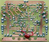
I finished my board layout all except for three (not one) hole.... it was fun drilling all 100 and some odd holes...
I'm going to start dry placing in all the parts i currently have (Or i might tin the traces), The possibility's are endless. I currently don't have any of the transistor or any of the high wattage resistors (Or even the high voltage capacitors).
If I'm not to lazy ill post some pictures
I'm going to start dry placing in all the parts i currently have (Or i might tin the traces), The possibility's are endless. I currently don't have any of the transistor or any of the high wattage resistors (Or even the high voltage capacitors).
If I'm not to lazy ill post some pictures
Last edited:
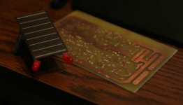
Got around to it
Here's some pictures that i have of the parts (the little amount that i have) and the board layout in all its messy glory... Oh yes, and a solar bug, little thing has been creeping in my crawl space!
You might not be able to see it in the pictures, but i have in fact missed four holes that i haven't drilled (and three extras on the ground track).
Cheers,
Kurtis
Here's some pictures that i have of the parts (the little amount that i have) and the board layout in all its messy glory... Oh yes, and a solar bug
, little thing has been creeping in my crawl space!You might not be able to see it in the pictures, but i have in fact missed four holes that i haven't drilled (and three extras on the ground track).
Cheers,
Kurtis
Attachments
very happy to say that a few greek friends are allready working on the construction ...the subject is presented also in a greek speaking forum and any day i will redirect pictures of the amps
anyday i am going also to "come in" with mine ...but too busy to produce it right now
regards sakis
anyday i am going also to "come in" with mine ...but too busy to produce it right now
regards sakis
- Status
- This old topic is closed. If you want to reopen this topic, contact a moderator using the "Report Post" button.
- Home
- Amplifiers
- Solid State
- Dx Blame ST - Builder's thread - post pictures, reviews and comments here please.