 I am sorry for the confusion.
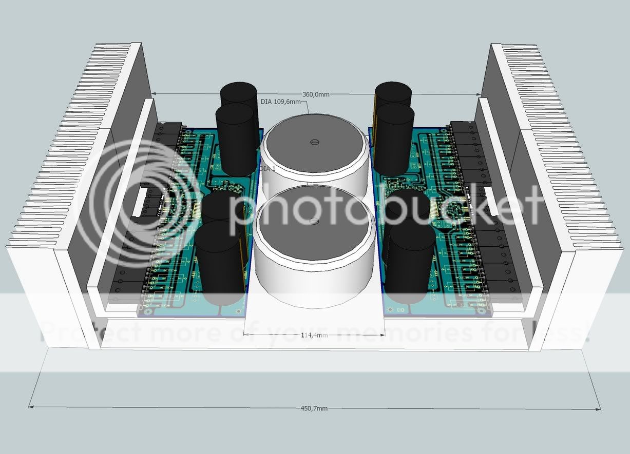
I have faced some troubles because "L" shape adaptors
Supercharged L adaptor heat transference issues - YouTube
I have tried thermal grease...also three screws... also Mica insulator...and no good result...thermal compound was i between " L " adaptor and main heatsink..also i have used to transistors.... result was a little bit better but the trouble continued...then i have cleaned transistor with kerozene and re-installed (thermal compound produces a lot of dirty...mess all things around)
regards,
Carlos
Last edited:
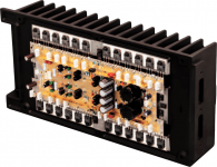
I am having fun with some toys...some ICs removed
From automobile radios:
One watt IC TDA2003 - YouTube
regards,
Carlos
From automobile radios:
One watt IC TDA2003 - YouTube
regards,
Carlos
OPTIMUM CASE DESIGN . .
@ CaféNoir,
As I reapply in the post 251 I wonder to ask You if You can produce an Image size like in Yours latest post 281 but with my suggestions below I repeat once more here so it will then be more evidently visible on the picture what are my suggestions, so for the power amp possible the most optimum solution, of course, and not the cheapest one.
1. PCB boards flush to the ALU Heat-sinks and rotate vertically PCB boards that trannies become at a bottom instead at the top !
- This way mounted OP semis will be at the bottom of the H_sinks so the term. convection would be at its best possible NO L BRACKET at all. Transistors are mount directly to the heat-sinks and theirs legs nicely round 90 deg. up. then all should be (mounted on the heat-sinks . . screwed & tightened with all needed supporting hardware firstly... On the PCB boards should be mounted the appropriate standoffs, screw them on to PCB and now insert the PCBs on top the the previously mounted transistors on the heatsinks, with legs of transistors come throe holes on the PCB, now solder them.
- Than for best design practice the PSU Elkos from the main Amp PCB boards should be mounted on separate PCB BOARDS or hardwire them ... they mus be mounted vertically because of electrolyte inside so mounted this way they can do their work 100%. Appropriate min capacity of Elkos should be 60K uF @ each CH supply side for this amp if it is to be as designed. Please move also the OP Coils + Res. directly to SPKR binding posts - this way You removing strong Magnetic pulses (coils generate) from the AMP Board ! Look at the Acuphase designs and You'll see how they do. . . the Masters.
2. extend the height of the heat-sinks so the internal height would be min 150 mm for the diameter size of a standard shielded min. 750VA toroid or R Core transformer!
3. extend deep of the case (two 150 mm Fisher H_sinks) to accommodate 2 pcs toroid transformers min. 750VA each !
4. make an 2 mm Fe L or even better an all closed U bracket for the toroids or R Cores and mount them "INSIDE" (two 750VA toroids) vertically ! Such an mounting arrangement brings also a quite reduced EME - a strong magnetic fields from the transformers.
5. Now You have plenty of room for the missed additional PSU PCB boards with min 60K uF of smoth. capac., the rectifiers, start up & protection boards with assoc. small VA transformers etc.. etc.

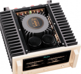
And here some more info from the masters of art
Pictures will tell more than 1000 words.
Regards,
Romero
[image][/image]
@ CaféNoir,
As I reapply in the post 251 I wonder to ask You if You can produce an Image size like in Yours latest post 281 but with my suggestions below I repeat once more here so it will then be more evidently visible on the picture what are my suggestions, so for the power amp possible the most optimum solution, of course, and not the cheapest one.
1. PCB boards flush to the ALU Heat-sinks and rotate vertically PCB boards that trannies become at a bottom instead at the top !
- This way mounted OP semis will be at the bottom of the H_sinks so the term. convection would be at its best possible NO L BRACKET at all. Transistors are mount directly to the heat-sinks and theirs legs nicely round 90 deg. up. then all should be (mounted on the heat-sinks . . screwed & tightened with all needed supporting hardware firstly... On the PCB boards should be mounted the appropriate standoffs, screw them on to PCB and now insert the PCBs on top the the previously mounted transistors on the heatsinks, with legs of transistors come throe holes on the PCB, now solder them.
- Than for best design practice the PSU Elkos from the main Amp PCB boards should be mounted on separate PCB BOARDS or hardwire them ... they mus be mounted vertically because of electrolyte inside so mounted this way they can do their work 100%. Appropriate min capacity of Elkos should be 60K uF @ each CH supply side for this amp if it is to be as designed. Please move also the OP Coils + Res. directly to SPKR binding posts - this way You removing strong Magnetic pulses (coils generate) from the AMP Board ! Look at the Acuphase designs and You'll see how they do. . . the Masters.
2. extend the height of the heat-sinks so the internal height would be min 150 mm for the diameter size of a standard shielded min. 750VA toroid or R Core transformer!
3. extend deep of the case (two 150 mm Fisher H_sinks) to accommodate 2 pcs toroid transformers min. 750VA each !
4. make an 2 mm Fe L or even better an all closed U bracket for the toroids or R Cores and mount them "INSIDE" (two 750VA toroids) vertically ! Such an mounting arrangement brings also a quite reduced EME - a strong magnetic fields from the transformers.
5. Now You have plenty of room for the missed additional PSU PCB boards with min 60K uF of smoth. capac., the rectifiers, start up & protection boards with assoc. small VA transformers etc.. etc.
And here some more info from the masters of art
Pictures will tell more than 1000 words.
Regards,
Romero
[image][/image]
Attachments
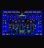
my version?
for you carlos thanks for teaching me.
for you carlos thanks for teaching me.
Attachments
SOUND_Rays, I will try your suggestions, as well as other possible layouts I have thought about. Unfortunately I am at work now, I will try as soon as I get home.
One question: is mounting the PSU caps vertically away from the boards (UNlike the Accuphase you showed as an example, if I understood correctly) really necessary? It could complicate the build quite a bit.
One question: is mounting the PSU caps vertically away from the boards (UNlike the Accuphase you showed as an example, if I understood correctly) really necessary? It could complicate the build quite a bit.
ok
im working on it and almost finish.checking it on gerber viewer online.i will send it to your email and also i have to check some pads and make some small edit.and also can you check clearance of mkt capacitors and power output transistor if exact in size.i use 5mm in mkt.
Send them to me...to my email.
This can be copied and pirates will produce and will sell in Ebay...i do not want to make pirate's life easier.
regards,
Carlos
im working on it and almost finish.checking it on gerber viewer online.i will send it to your email and also i have to check some pads and make some small edit.and also can you check clearance of mkt capacitors and power output transistor if exact in size.i use 5mm in mkt.
@ CaféNoir,
On the main PCB boards let stay instead big Caps only 2 x 4700uF or 2x 2200 uF caps and use RL filters in between on each side. The main big Caps eg 4 x 10 000uf each side should be mounted in a perfect vertical position, possible directly to the bottom of the chassis with assoc. hardware fasteners so the screw or solder terminals will be at the top. Than it is possible to hardwire them with additional RL filter in between each 20K uF and go with heavy 3 mm solid transformer enameled wire to the PCB boards. This way the main PSU capacitors would operate at theirs best possible life cycle and aging effect would be minimal, and as a bonus the vibrations they produce under heavy current demands won't be emitted to the PCB Boards - less mechanical inducted noise to the sensitive small electrolytic, silver micas ... and capacitances to pcb traces and to small signal transistors as well. The Masters of Art uses the vibrations dampers wherever they can - the result . . . unparalleled sound perfection even to biggest and most acclaimed names. . .
Regards,
Romero
Interesting.... vibration dampers....i know people from your place
or surrounding countries...Croatia.... Slovenia.... Serbia and some other places uses stands to speakers...some of them say that if you use a stone is better than wood..there are a lot of beliefs about..some of them make sense.
Once someone told me something about:
- "An amplifier, when playing in the floor, will sound better than when it is playing over a table or something alike"
Well...maybe...for reasonable levels of sound.... in our case..the power is so huge that you will have to install your amplifier in the moon to avoid vibrations.... everything will shake...the amplifier, boards, table, floor, ceiling, walls, woods, ground and yourself..also your ears will shake and will modulate audio too.
regards,
Carlos
For sure vibrations are important...at the end they are sound
I am watching something that has a lot of worries about vibrations..in this case is the propagation of vibrations.
The Bridge part 2 - YouTube
regards,
Carlos
I am watching something that has a lot of worries about vibrations..in this case is the propagation of vibrations.
The Bridge part 2 - YouTube
regards,
Carlos
3d layout
just having fun.
for you carlos thanks for teaching me.
just having fun.
Attachments
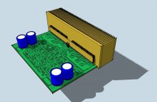
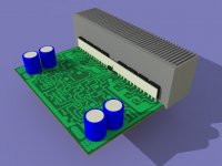
google sketch up
my office mate did it.Thank you very much.
What is this software you're using dear Tayag?
regards,
Carlos

Fuses .... values depending the speaker you will use
FUSES TO EACH CHANNEL – MKIII-Hx
- If you will use your amplifier with 8 ohms speaker, then use 3A to each rail and 6A in series with the speaker
- If you will use your amplifier with 4 ohms speaker, then use 6A to each rail and 12A in series with your speaker
- If you will use your amplifier with 2 ohms speaker, then use 10A to each rail and 20A in series with your speaker
regards,
Carlos
- Status
- This old topic is closed. If you want to reopen this topic, contact a moderator using the "Report Post" button.
- Home
- Amplifiers
- Solid State
- Dx Blame MKIII Supercharged will soon be released