I am not sure about the bigger boards with L-brackets.
As Mr. Carlos said, it means less space to install in a standard enclosure, which will have quite big transformers inside as well. You lose space of the transistors, and of the brackets thickness.
Also, I think the first slimmer version is more versatile if one wants to install the boards vertically, attached directly to the heatsinks, allowing a compact solution.
Not to mention the loss of heat transfer induced by brackets.
It all depends what the people at my groupsbuy wants.When you build a high power amp you don't instal everything in a small case.If they want the smaller boards it's OK by me.
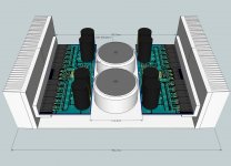
I will make some 3D models of case layouts, and see what comes up
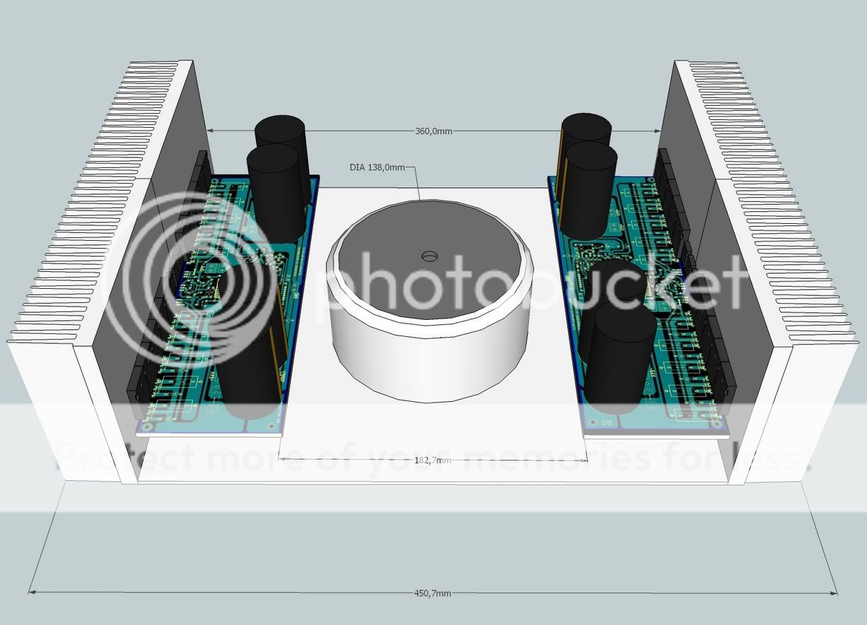
Here are some some basic 3D layout models to investigate boards dimensions.
I have used a fairly standard Hifi2000 pesante dissipante 3U for the illustration. The reason I chose Hifi2000 is that these have common dimensions, and are widely available, so this makes a good reference. I added PSU caps and transistors for cosmetics.
This first layout features the slim board without the L-brackets. There is room for a 500VA transformer of standard diameter.
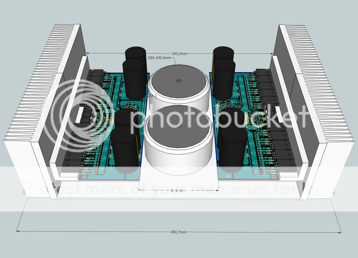
Next features the large board with L-brackets. Space is considerably reduced. The 500VA transformer does not fit.
One solution is to go for dual smaller transformers (around 225VA), which fit very tightly between the boards. But there is very little flexibility on the size of the transformers. For instance, I like to use shielded transformers, which adds to the diameter. Not possible here.
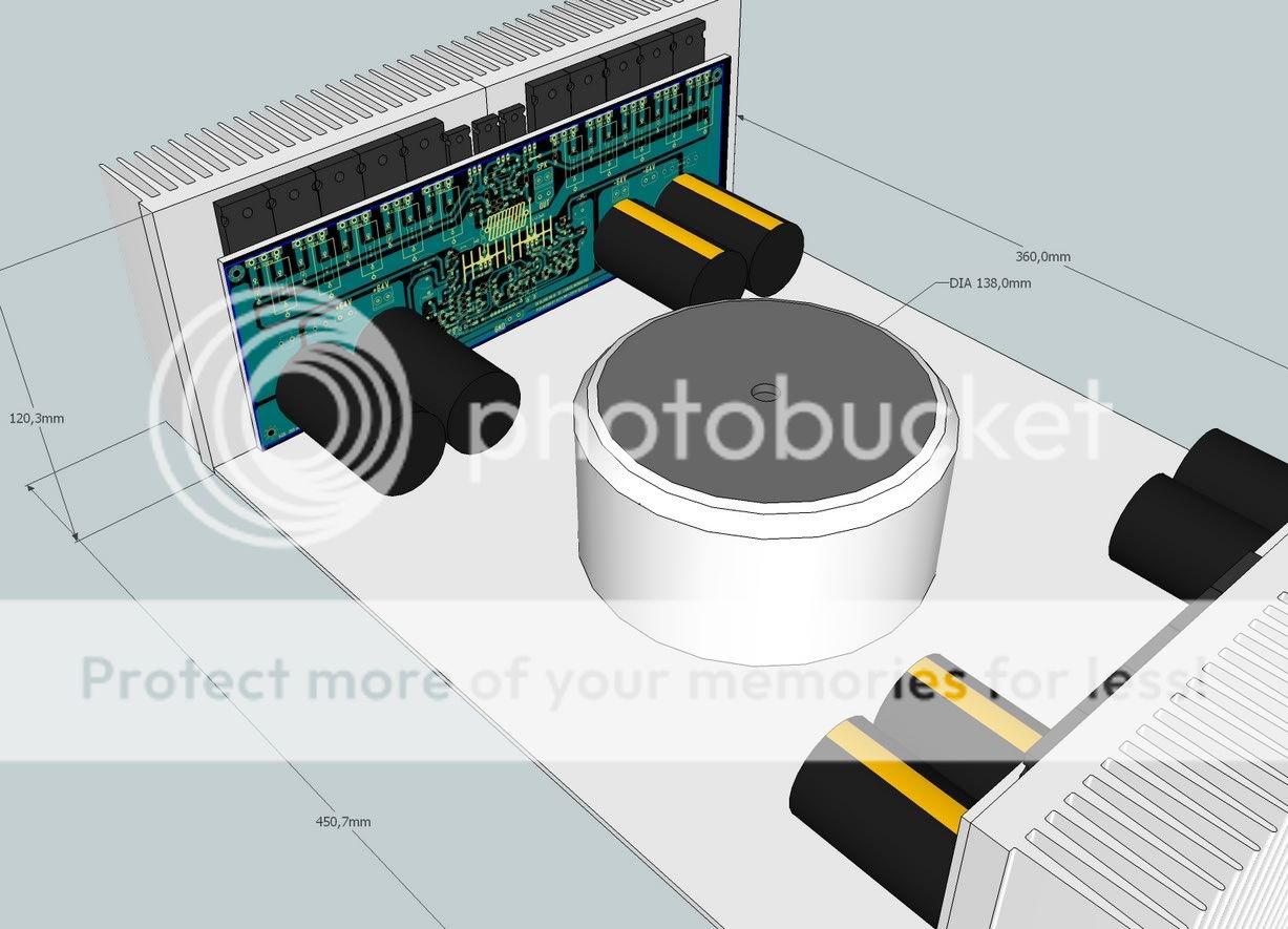
Next, let's investigate the vertical mounting. Vertical mounting is managable with the slim board, with a little bending of the leads of the transistors.
Large boards will hardly fit in the 3U case. A 4U case will be needed, which will lead to sub-optimal space management.
So, my take on this is that the L-bracket mounting has more disadvantages than advantages in this application.
I have used a fairly standard Hifi2000 pesante dissipante 3U for the illustration. The reason I chose Hifi2000 is that these have common dimensions, and are widely available, so this makes a good reference. I added PSU caps and transistors for cosmetics.
This first layout features the slim board without the L-brackets. There is room for a 500VA transformer of standard diameter.
Next features the large board with L-brackets. Space is considerably reduced. The 500VA transformer does not fit.
An externally hosted image should be here but it was not working when we last tested it.
One solution is to go for dual smaller transformers (around 225VA), which fit very tightly between the boards. But there is very little flexibility on the size of the transformers. For instance, I like to use shielded transformers, which adds to the diameter. Not possible here.
Next, let's investigate the vertical mounting. Vertical mounting is managable with the slim board, with a little bending of the leads of the transistors.
Large boards will hardly fit in the 3U case. A 4U case will be needed, which will lead to sub-optimal space management.
So, my take on this is that the L-bracket mounting has more disadvantages than advantages in this application.
Hi Meanman ,
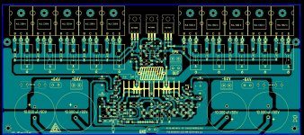
I have adjust to correct size , 265 mm X 115 mm
Alex.
Sweeet ...alex ..

Cafe Noir , I dont like the last layout , the vertical mounting have the outputs at the top, this will have issues with cooling IMO. Guys this is a big amp , the others look fine and most likely this amplifier might require 2 chassis and or for sure large custom case . Please do not compromise the boards to try and fit in some kind of micky mouse cage , this is a big bwoy amp, please keep it as such ....
Last edited:
@ CaféNoir,
Some possible suggestions for a long term trouble free AMP serving the purpose.
1. rotate vertical AMP PCB boards 180 deg. that trannies become at a bottom instead at the top !
- This way mounted OP semis will be at the bottom of the H_sinks so the term. convection would be at its best possible. But please STAY AWAY FROM ANY KIND mounting of OP Trannies to an L Brackets and thus compromising termall convection & T. tracking !! for this kind of power !! L bracket is a DESIGN FLAW !!
Than for best design practice REMOVE PSU Elkos from the main Amp PCB boards. They just haven't to be mounted horizontally but instead they must be mounted absolutely VERTICALLY ! ( so maybe this is a call for another separate PSU PCB boards with appropriate min 60K uF @ each CH supply side & unconditionally move the OP Coils + Res. directly to SPKR binding posts this way removing strong Magnetic pulses (they generate) from the AMP Board ! Look at the Acuphase designs and You'll see how dey do. . . the "Masters of Art"
2. extend the height of the heat-sinks so the internal height would be min 150 mm for the diameter size of a standard shielded min. 750VA toroid or R Core transformer!
3. extend deep of the case (two 150 mm Fisher H_sinks) to accommodate 2 pcs toroid transformers min. 750VA each !
4. make an 2 mm Fe L or even better an all closed U bracket for the toroids or R Cores and mount them "INSIDE" (two 750VA toroids) vertically ! Such an mounting arrangement brings also a quite reduced EME - a strong magnetic fields from the transformers.
5. Now You have plenty of room for the missed additional PSU PCB boards with min 60K uF of smoth. capac., the rectifiers, start up & protection boards with assoc. small VA transformers etc.. etc.
6. All the mentioned suggestions called for the min. necessary respect to an AMP designer, than to Yours $$ investment in the all parts needed for building the amp and it (the AMP) definitely DESERVE THE CHASSIS it NEED so no saving $$ on this last crucial parameter at all.
This way long term marriage is assured and many Years of Amp serving the music with kind hope all builders of this amp will enjoy it daily.
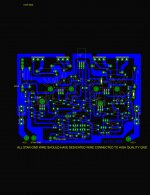
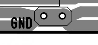
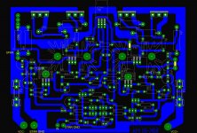
Remove this text about star ground... this confuses me
and i have 51 years experience building amplifiers... star ground is just something fashion...a point where we connect our ground to avoid issues as ground loops.
We need a SINGLE POINT where to collect ground.... that point should be marked as ground... ONE ground mark only.
I have asked you before to do this way.... seems you missed what i have asked.
Please, do not post text in yellow as this will generate confusion as i told you before.... gimmick... that story of star ground is just something obvious that became "the big thing"...in the reality is is simple, basic and obvious...just a single point in the chassis (mainly not to turn board awfull having a lot of wires getting out from the circuit board) where wires are joined...usually nearby the power transformer...a center tap is connected to the chassis using bolts and nuts and there you have your central ground (star ground)
Also i have asked you do identify yourself...i cannot see your country...this was not informed.
Please, you seem have some kind of lack of attention...i asked you, before, to remove mentions about star ground...this is just something that creates a lot of controversies as we have a lot of crazy fanatics that has beliefs about these things and they may come to our nice thread to bother discussing these foolishes...and you will be the one generated...please, be attention reading with care the email messages i send you.
This project is not to be made in a hurry, not needed to be fast....slow down...i will use new boards, different boards, new layout designer, another layout designer (maybe two) in November.
Thank you by your effort, goodwill, enthusiasm and cooperation...i am happy watching you studying layout design the way you're doing...but i do think we have to communicate better...there's a lack of communication in between us.... message was already sent asking you not to put a lot of ground marks in the board..also asked you to inform your country.
MKIII is another amplifier Joel....this one had important modifications in it's circuit and now has the sufix Hx.... MKIII-Hx is the amplifier.
regards,
Carlos
Attachments
Last edited:
Beautifull 3D images dear CaféNoir..... i will post something about transformer size
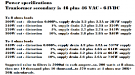
This is the main problem as this amplifier can reach 1 Kilowatt each channel (distorting) this may need a huge transformer ... a big one.... a large one.
I would like to have your attention folks about the transformer size.... to use this amplifier as a terminator, an earthquake generator, then you will need 1370 watt transformer to each channel... 2 big ones..they are big..and see the electrolytic condenser bank will be very big too.
People can use smaller...to allow them to have good power in 8 ohms only...then we will not have too much room problems to install all stuff inside a standard case.
Observe that to use it professionally, to be generating sound to parties, stadiums, theater, Public Adress..then you will need two power transformers to supply the energy this monster can handle...so... people must decide first the application, the destination, the kind of use they will have..then to select transformer power and think about enclosure size..if will build dual mono or stereo.
This amplifier does not accept 1 ohm.... distortion increases, efficiency reduces and we have a lot of intermodulation distortion.. please, do not use 1 ohm.
regards,
Carlos
Attachments
Last edited:
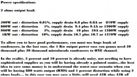
I have posted all these power specifications, currents, condenser capacitances
... and many other things because beginners.... young guys starting to learn or old folks starting to use soldering iron after their retirement.
The main idea that must be understood is that we cannot create energy.... power amplifier output power depends on the power supply...our amplifier is 50 to 63 percent efficient because it is a Class AB amplifier...so, almost half of the energy provide by the power transformer is transformed in audio (efficiency).... so, if you select a 500 watts transformer or 500 VA transformer (VA is Volts multiplied by Amperes...and this is also Watts..so... VA=Watts)... selecting this one, an already huge unit, you will have 250 watts of audio or a little bit more.... do not matter what you do....no way to have much more than that because power transformer will not provide more..so, you can reduce your speaker impedance to 4 ohms, 2 ohms and even 1 ohms and you will not have more much more than aprox. 250 wiskies.
So, if you use a single power transformer, feeding two channels, then each channel will be able to put out 125 watts (more or less)...if both channels will be working same time..then the limit will be 125 watts to each one of them (both channels driven).... of course one channel muted will let energy flow to the other and this way the other channel, will be able to deliver 250 watts.
So, this is the main decision you should take..what supply size you gonna use.... if you gonna use two power transformers, two rectifiers or if you will use a single supply..also you demand or current.
These images posted in the previous post are to help you to decide what will be the power you gonna use...fuses size, transformer specification, condensers..all that is there posted for you to see.
There's no magic...we cannot create energy...all stuff comes from your power supply.... power amplifier power is the power your power supply can provide ... there's no 5 kilowatt amplifier while using 4 kilowatt supply..if they work in class D you may have almost 4 kilowatt while using 4 kilowatt supply...if you are running class AB, maximum will be 2 to 2.5 Kilowatts.
I hope this will help, at least may be useful to beginners.... you, skilled guy, do not need these instructions.
regards,
Carlos
Last edited:
Dear Joel Tayag sent message
He is from Phillipines and he is working in Saudi Arabia.
A nice good looking fanatic... alike all of us...fanatics...we are not usually good looking...but for sure fanatics ... heheheheh
Comunications is a very complicated subject..some guys uses google translator..and this produce a big mess... we have this problem...we go to English, and it is not our native language.
regards,
Carlos
Attachments

Last edited:
We are tuned...we agree... we talk about... we decide discussing and voting
.... and this is why we are having success in our venture.
each new day we have one or two more guys ordering...we gonna do it... the music that should be playing now, as we are overcoming all troubles is:
- "Do not worry about a thing, because every little thing gonna be all right"
regards,
Carlos
.... and this is why we are having success in our venture.
each new day we have one or two more guys ordering...we gonna do it... the music that should be playing now, as we are overcoming all troubles is:
- "Do not worry about a thing, because every little thing gonna be all right"
regards,
Carlos
Last edited:
Well.... both ideas are good.... all them have advantages and disadvantages
one is smaller and you can install transistors below (under) the board...this will save even more space.
The other option is strong...the construction becames stronger.. but waste a lot of space and we will have HUGE thermal issues because heat transference...so... the "L" adaptor is nice but is also a big source of troubles.
In the other forum, half of guys (50%) there are Brazilians..at least the ones that have ordered boards are there waiting for MAKO, the amplifier that sank and is now a days at Titanic side.....all them good friends...and i know they will like with "L" bracket....in this forum we gonna let Byron decide, as he already have made arrangements with his board manufacturer...and the board offered was that way he arranged with the manufacturer..so...he can keep not to mess with all the work he has done.
Mako was a 2Kw per channel project that failed, and now it sank beneath the ocean next to the Titanic.
Also, if Byron decides to take to himself the work. and give a large step back, ordering to his manufacturer to produce other files (larger boards)....well...for me it is all right...
This question should be posted, by Byron, if he decide to ask... and to the ones have ordered boards in his group buy..he is the manager..he is the man...he decide.
Well...i am playing with a chip amplifier (IC) and i will return there to continue to play:
http://www.youtube.com/watch?v=isxHbA6BOYM
regards,
Carlos
Last edited:
- Status
- This old topic is closed. If you want to reopen this topic, contact a moderator using the "Report Post" button.
- Home
- Amplifiers
- Solid State
- Dx Blame MKIII Supercharged will soon be released