My question is what parts need to be attached to the "lifted" ground? If it is only the input ground, I have accomplished that already with my 10R resistor at the RCA. On the schematic, C4, C6 an C7 all also connected to the lifted ground. If that is necessary, there a few traces that need to be cut and some jumpers that need to be installed.
Based on your schematic, I'd say the input shield, R01, C04, C06 and C07 should be returned to the lifted ground and all else back to the star ground.
Issue is that as shown, some decoupling is connected there and also the VAS beta enhancer transistor and the current sources are all drawing current from this supposedly quiet point. These will all cause voltages to appear on the 10Ω resistor and end up as noise. Any decoupling or biasing should come from or be returned to the star ground.
Issue is that as shown, some decoupling is connected there and also the VAS beta enhancer transistor and the current sources are all drawing current from this supposedly quiet point. These will all cause voltages to appear on the 10Ω resistor and end up as noise. Any decoupling or biasing should come from or be returned to the star ground.
Hi Jason,
The original schematic shows just what you just suggested. However, the PCB I have is connected the way I showed on my altered schematic. I think what you are suggesting can be done but as noted above, will require cutting some traces and installing some jumper wires. Right now, I have a jumper installed where R30 (10R) is supposed to be and a 10R resistor installed at the RCA ground pin, lifting the input ground there. With the jumper installed at R30, everything but the input ground goes to star ground, including R01, C04, C06 and C07. This may be the reason there is still a slight hum. When I feel energetic I will pull the amp apart and see how much work it will take to correct it so it is hooked up like the schematic. I assume that is how it was simulated.
Blessings, Terry
Last edited:
Hi Jason,
The original schematic shows just what you just suggested. However, the PCB I have is connected the way I showed on my altered schematic. I think what you are suggesting can be done but as noted above, will require cutting some traces and installing some jumper wires. Right now, I have a jumper installed where R30 (10R) is supposed to be and a 10R resistor installed at the RCA ground pin, lifting the input ground there. With the jumper installed at R30, everything but the input ground goes to star ground, including R01, C04, C06 and C07. This may be the reason there is still a slight hum. When I feel energetic I will pull the amp apart and see how much work it will take to correct it so it is hooked up like the schematic. I assume that is how it was simulated.
Blessings, Terry
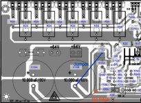
I think the issue is that C11 & C12 also go to the same ground as the signal input whether you jump R30 or not. So I agree that the traces that serve as the C11,12 ground should be separated from signal ground and returned to the nearby main filter cap ground traces instead.
Cannonica, please show me where i told the modifications will result in better sound?
I do think no one can show me that...and if i made this mistake, them let me know to allow me to correct the foolish i said.
I said and posted and written in the video comment lines, the modifications are made for the electronic "voyers"..the ones have worries about distortion into oscilloscope screen display....modifications are for this purpose.. to the ones wants to see better waveshape.
Watch audio graphic image to see if the waveshape are pretty, or if they are sinusoidal (perfect) or triangle or square...they are multiple shapes....perfection means nice image only...audio quality is another story.... listen guitar guys distorting and feeling good...what distortion means to one is different related what means to other.
I have never said the sound will be better.....for better sound go to original schematic.
Modifications is to "show" better clipping image.... dedicated, i repeat dear Cannonica, to the ones wants to view better waveform while distorting..for them, as the focus is "image"..this may help....but sound.....well...... another story.
If bootstrap was not important i would never installed into my amplifiers.... watch if Blameless is using it...it is there because the effect is lovely...but if the removal makes better image to some guys that wants that...well...i want them to be happy.... as they may give more importance to image than sound.
My new models will have switch to connect bootstrap on and off.... they will have also CCS.... you can do it... switch goes to electrolitic capacitor negative to ground..then you open the connection and close the connection with a simple two poles switch.
I said that i do not agree with people giving priority to "image" related to "sonic" performance...but i am always ready to behave alike a fire soldier to extinguish fire...if people complain about image..then i can prepare a solution..then they gonna be silent (i hope they do not complain about ...heheheheh)...this helps people to be stimulated to build my amplifiers if i succed to produce some silence into the critics mouth..... better image...then less criticism...
About ground loop and hum issues i cannot help because i am not competent, not skilled, not prepared to do so...as i have never faced such kind of troubles i have not learned how to fix the stuff.
Happy new year folks....uncle charlie from now on on vacation..... a Merry Christmas to all of you and listen music with Dx amplifiers to be more happy.
regards,
Carlos
Last edited:
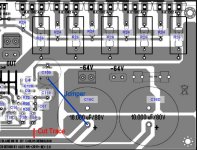
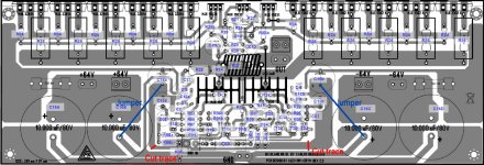
OK, I have looked over the boards and it seems that two trace cuts and two jumpers can solve the lifted ground issue. I am posting a couple illustrations for discussion. Please look them over and let me know if you see a problem with this change.
Thanks, Terry
Thanks, Terry
Attachments
Last edited:
Carlos,
The original measurements showed instability, the updates based on the test you performed shows the amp to be more stable on recovery, but there was no mention as to
1. thd vs noise
2. thd vs power output
3. thd @ rated power .
I have yet to see a Square wave at 10hz, 1k 10k , 20K ,30K , I think Cannonica did show some Squarewave a longtime ago , I'm not sure now .
As to sonics and with all due respect, i have yet to see anyone here with a setup capable of doing proper sonic evaluations , in that case i would like to see proper scope/bench measurements and since you did not mention , i will ask, is the thd higher or lower with your updates..
Regards
Last edited:
Carlos,
The original measurements showed instability, the updates based on the test you performed shows the amp to be more stable on recovery, but there was no mention as to
1. thd vs noise
2. thd vs power output
3. thd @ rated power .
I have yet to see a Square wave at 10hz, 1k 10k , 20K ,30K , I think Cannonica did show some Squarewave a longtime ago , I'm not sure now .
As to sonics and with all due respect, i have yet to see anyone here with a setup capable of doing proper sonic evaluations , in that case i would like to see proper scope/bench measurements and since you did not mention , i will ask, is the thd higher or lower with your updates..
Regards
Hi Wayne,
I have to wonder what you mean when you say " proper sonic evaluations". Just what kind of setup are you talking about? I have several different speaker cabinets ranging from bookshelf to studio monitors and each and every one sounds different. Combining them even gives more choices. The only way I know of doing sonic evaluations is to do blind testing using a given speaker combination and then switching between amps. How do you suggest one makes a proper sonic evaluation?
Thanks, Terry
OK, I have looked over the boards and it seems that two trace cuts and two jumpers can solve the lifted ground issue. I am posting a couple illustrations for discussion. Please look them over and let me know if you see a problem with this change.
Thanks, Terry
Hi Terry-
That's just what I had in mind and am planning to do. I think at the same time it would be wise to move the R17 ground to the star point. I don't think the bootstrap capacitor is relevant to the hum problem but it does seem to have some effect on clipping symmetry.
OK, I have looked over the boards and it seems that two trace cuts and two jumpers can solve the lifted ground issue. I am posting a couple illustrations for discussion. Please look them over and let me know if you see a problem with this change.
Thanks, Terry
I agree with your trace cut-outs. Position of R08b and R17 would need to be changed as well to connect to the star ground...
Carlos, I understand and agree with your comments.
I've observed three things:
-Assymetrical clipping: I don't care and I think it's part of the "personality" of this amp. It really sounds sweet. People shoudn't care about this and they should even ignore it to enjoy that delicious amp.
-Negative rail sticking: I don't know if you used a baker clamp to recover from sticking in your filmed clips. I would recomment whoever build this amp to use one in order to prevent damage to other equipment under heavy clipping (speakers)
- 120Hz buzzing (North America, 100Hz in some other countries): well, this one is simply annoying, and I think it's the main subject these times. I's hard to determine if it's due to the board layout with its somehow awkward lifted ground configuration or what.
Nothing less nothing more...
Mart.

I fired up my MkIII for the first time today: no 120hz hum whatsoever. There is a very slight hiss when I put my ear up to the loudspeaker with no music playing - but I'm still tidying up the wiring and grounding and will report back again once I've played a bit more.
My main cap bank is off board. 4x 4700uf per rail. Seperate cap bank and bridge rectifier per channel; shared transformer. I have 1000uf caps onboard where the bulk caps normally go.
I haven't done the lifted ground or any other mod.
EDIT : the sound is fantastic. Deep, powerful bass; beautiful treble and crystal clear mid-range. It sounds purposeful with real presence whereas some very high-end amplifiers I've auditioned have a somewhat restrained "lean" sound. If this is harmonic distortion I don't care because I like it :-D
Last edited:
- Status
- Not open for further replies.
- Home
- Amplifiers
- Solid State
- Dx Blame MKIII-Hx - Builder's thread