@ Andrew T.
Carlos has fun in is heart. You may help people. The reason i see your help is just to blow your trummpet and mostly out of tune. It is good to put the books down and HAVE some FUN before you Die.
ps I have never had the displeasure of listening to any of your published amplifiers. I concider that to be blessing in disguise.
Experimentation is the most powerfull way to learn.
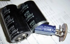
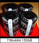
35diam * 50 tall, seems small for an audio cap of 10mF & 80V.
Have you checked ELNA data to see what the size is?
Hi Andrew,
I have checked the Elna datasheet but I can't find the Elna For audio 10000uF 80volt.
I email also Elna America to find out if they are fake.
It's worry's me the fake things you can buy from Ebay that comes from China.
Is there a good alternative for those 10000uF 80 volt caps on the Dx Blame MKIII-Hx board?
Have somebody experience with good 10000uF 80 volt quality caps on this place of the board?
What is the most important, if I purchase the emitter resistors?
What brand emitter resistors should I order?
Non inductive resistors?
I have read a lot about it but the one says this and the other says that.
Last week I have done a second order, here you see the parts:
6x Elna Silmic II Capacitor 47uF 100V 12.5x25 mm
2x Elna Silmic II Capacitor 22uF 100V 10x20 mm
2x Elna Silmic II Capacitor 220uF 100V 18x40 mm
6x Elna Silmic II Capacitor 100uF 100V 16x25 mm
2x Takman Resistor 47K 0.25 Watts
4x Takman Resistor 220R 0.25 Watts
2x Takman Resistor 68R 0.25 Watts
4x Takman Resistor 100R 0.25 Watts
2x Takman Resistor 8K2 0.25 Watts
2x Takman Resistor 390R 0.25 Watts
4x Takman Resistor 2K2 0.25 Watts
2x Takman Resistor 47K 0.25 Watts
4x Takman Resistor 22R 0.25 Watts
4x Takman Resistor 470R 0.25 Watts
2x Takman Resistor 330R 0.25 Watts
4x Takman Resistor 1K 0.25 Watts
2x Takman Resistor 680R 0.25 Watts
2x Takman Resistor- 10R 0.25 Watts
2x Takman Resistor 150R 0.25 Watts
2x Takman Resistor 10R 1 Watts
Regards,
Rudy
Attachments
Last edited:
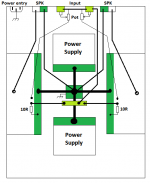
I can't draw like you two, so I'll try to describe Leach's alternative method.
Connect the two input socket returns together. They need to be very close to each other, to do this successfully.
Run the main Signal Ground from the twinned input sockets to the Main Audio Ground (MAG).
Run the two amplifier inputs (Signal Hot & Signal Return) from PCB to it's respective input socket. Repeat for the other channel.
Now the amplifier can measure the difference in voltage across the input socket and process that input signal.
Draw this on your diagram.
Move the Spkr Return. Run the new Skpr Return from return terminal to MAG. Now add that to your diagram.
Go back to the PCB and ensure the PCB Power Ground runs direct to MAG. repeat for other channel.
Add these to your diagram.
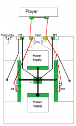
Look at your diagram.
Trace out the circuit that the input signal follows to return to the Source.
Trace out the circuit that the spkr signal follows to return to the PCB.
Trace out the circuit that the Power Supplies follow to return to PSU Zero Volts.
Trace out the circuit that the transformer currents pass to return to the transformer.
Note:
1.) the long route of the Signal circuit. This must have a low loop area.
2.) are any circuits sharing a length of wire/trace?
Leach suggests that the voltage reference connection from Signal circuit to Spkr circuit is HF restricted by high inductance. He suggests that there needs to be a low inductance path between these two circuits. He adds a low value resistor that must necessarily have short traces between Spkr circuit and Signal circuit.
I have found this method to give the quietest result for most but not all source types. The few that are not of the quietest are only slightly affected by hum.
I have experimented extensively and cannot find a solution that is completely HUM FREE for all source types. Usually each alternative has at least one "Achilles heel" with more than slight hum.
I hope this helps.
Read Leach, Read Davenport. Read Self. They all talk from the same bible.
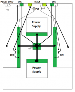
Connect the two input socket returns together. They need to be very close to each other, to do this successfully.
Run the main Signal Ground from the twinned input sockets to the Main Audio Ground (MAG).
Run the two amplifier inputs (Signal Hot & Signal Return) from PCB to it's respective input socket. Repeat for the other channel.
Now the amplifier can measure the difference in voltage across the input socket and process that input signal.
Draw this on your diagram.
Move the Spkr Return. Run the new Skpr Return from return terminal to MAG. Now add that to your diagram.
Go back to the PCB and ensure the PCB Power Ground runs direct to MAG. repeat for other channel.
Add these to your diagram.
Look at your diagram.
Trace out the circuit that the input signal follows to return to the Source.
Trace out the circuit that the spkr signal follows to return to the PCB.
Trace out the circuit that the Power Supplies follow to return to PSU Zero Volts.
Trace out the circuit that the transformer currents pass to return to the transformer.
Note:
1.) the long route of the Signal circuit. This must have a low loop area.
2.) are any circuits sharing a length of wire/trace?
Leach suggests that the voltage reference connection from Signal circuit to Spkr circuit is HF restricted by high inductance. He suggests that there needs to be a low inductance path between these two circuits. He adds a low value resistor that must necessarily have short traces between Spkr circuit and Signal circuit.
I have found this method to give the quietest result for most but not all source types. The few that are not of the quietest are only slightly affected by hum.
I have experimented extensively and cannot find a solution that is completely HUM FREE for all source types. Usually each alternative has at least one "Achilles heel" with more than slight hum.
I hope this helps.
Read Leach, Read Davenport. Read Self. They all talk from the same bible.
Last edited:
I would like to inform our friends that Meanman intend to open
a second round of group buy to provide the MKIII Hx to forum folks...not only in this forum but also in other international foruns.
Meanman is an old and traditional friend and member from the Dx Corporation, someone that has built almost all models..he can open group buys anytime, anywhere and to provide any Dx amplifier.
He has my support, my thanks and my blessings.
regards,
Carlos
@Rudy:
What about authentic Nichicon 10.000µF / 80 V, Type: LLQ1K103MHSC
http://www.abload.de/img/joe002opdl.jpg
One capacitor costing less than 3€.
The diameter of this capacitor is 35 mm. Does it fit on Alex' PCB?
Source is: Neuhold Elektronik die Fundgrube für den Hobby-Elektroniker Elko 10.000uF/80V
Best regards - Rudi
What about authentic Nichicon 10.000µF / 80 V, Type: LLQ1K103MHSC

http://www.abload.de/img/joe002opdl.jpg
One capacitor costing less than 3€.
The diameter of this capacitor is 35 mm. Does it fit on Alex' PCB?
Source is: Neuhold Elektronik die Fundgrube für den Hobby-Elektroniker Elko 10.000uF/80V
Best regards - Rudi


Dear Juan Vargas ... our friend Meanman is studying what to do
soon we gonna have some return from him, and them this gonna be published and i will send you email informing for sure.
He is thinking to make some small modifications... about clearance to heatsink (on board ones) ... some tracks may be enlarged .... suggested transistor model numbers will be printed into the silk screen .... board will be painted red both sides... and so on.
Also Byron can open a second round if he decided to do .... this way we gonna have more boards available in a matter of a couple of months to come.
No circuit change.... the problem related on board heatsink (clearance to produce room to a bigger ones, or to install them in the main heatsink, or to fix them below the board) will be solved too.
Meanman is free to make small modifications, making interface with Alex mm or changing himself together the board manufacturer company that usually produce tests in his layouts .... he will suggest some ideas ... but for sure the amplifier will be the same unit with minor modifications into the pcboard layout.
As i had that surprise... the heatsinks not large enough ... then i decided to make a step back, or to work in the most safe side... assembling the board myself prior to deliver them to forum folks... to avoid surprises i will be the first to assemble and test the circuit assembled into the same board you will receive.
regards,
Carlos
Last edited:
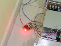
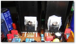
Testing in progress
I made a Toggle switch using 555 timer, circuit can be found in other website, also i finished Ostripper softstart hook it up altogether for checking and it works the way it supposed to be, very happy with the outcome. I like those "circle green light"
Here are some pics of my progress, messy but satisfying.
Attachments
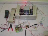
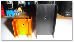
Nice work Junie.... i would like to show Juan Vargas pictures
He will use 54 volts supplies....he bought a larger heatsinks as you can see and installed the CCS and VAS into the larger heatsinks.
Uploaded with ImageShack.us
Good.
regards,
Carlos
He will use 54 volts supplies....he bought a larger heatsinks as you can see and installed the CCS and VAS into the larger heatsinks.
An externally hosted image should be here but it was not working when we last tested it.
Uploaded with ImageShack.us
Good.
regards,
Carlos
Attachments
I made a Toggle switch using 555 timer,
Junie , when you say that , i'm assuming you used a 555 timer in some way as a relay circuit because those switches are only rated at 2A ? am i correct and if so , please tell me how . i love those switches but their max amp rating is such a limiting factor .
cheers Woody
Junie , when you say that , i'm assuming you used a 555 timer in some way as a relay circuit because those switches are only rated at 2A ? am i correct and if so , please tell me how . i love those switches but their max amp rating is such a limiting factor .
cheers Woody
Hey Woody, yeah 555 as pre driver and used SSR instead of Relay.
More info can be found here: Toggle ON / OFF Switch
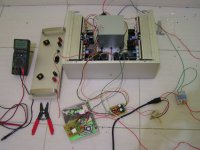
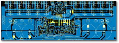
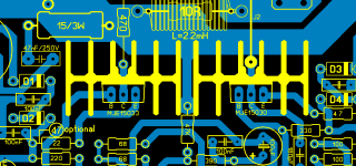
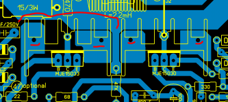
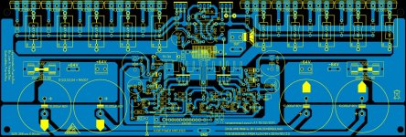
vargasmongo personal layout changes "heat sink'
Today a did some changes on my layout, I change the heat sink for a taller ones and the silk screen too, of course this is Alex MM layout don't get me wrong that is the man! well I got to keep looking analising and all that, I hope you guys like my ideas, "I hope so" lol , alright guys have a good one.
Today a did some changes on my layout, I change the heat sink for a taller ones and the silk screen too, of course this is Alex MM layout don't get me wrong that is the man! well I got to keep looking analising and all that, I hope you guys like my ideas, "I hope so" lol , alright guys have a good one.
Attachments
- Status
- Not open for further replies.
- Home
- Amplifiers
- Solid State
- Dx Blame MKIII-Hx - Builder's thread