I just got the heat sink today, it take forever to get parts here in Puerto Rico ! well I got to have patience.
Juan those heatsinks are a bit smaller i reckon but use it for a while and see if it will burn your fingers then replace it
")
That cool I hope didn't get burn
well let see how is going to react I just going to use +54 -54V power suppy
Juan those heatsinks are a bit smaller i reckon but use it for a while and see if it will burn your fingers then replace it
well let see how is going to react
I just going to use +54 -54V power suppy
Last edited:
They will be very hot Juan, as i told before.
If you cannot or do not want to substitute them for bigger ones, then try to reduce current the way i have explained in this same thread.
Using lower voltage feeding your power amplifiers you may be rid from the excess of heat.
A good idea is not to use insulator in these transistors that goes to the small heatsinks, the vertical ones...but they must be insulated one related the other, they cannot touch one to the other to avoid dangerous shorts...or you screw them into the board or use rubber insulators to avoid heatsinks to touch one to the other.
Non insulated heatsinks have colector voltage on them...so.... if they touch one each other you gonna have shorts and damage..... by the other side, the use of insulators will avoid you to have shorts, but also will maintain your temperature higher than if you use transistor directly attached to these small heatsinks while using thermal compound.
Without the silicon rubberized insulator you shown, the heat transference will be better...the insulator is a resistance to heat transference to the heatsinks and use to maintain the transistor at highest temperatures.
Be attention.... these transistors heatsinks cannot touch one each other...insulators as you shown as good to avoid shorts but they keep the temperature too much high for 64 volts or more supply voltages....maybe your case of 54 will keep you rid of these troubles.
I have pointed and published something about this... sadly some guys have not read and i could see them using small heatsinks..... i am afraid some of them may have troubles..these small heatsinks are not good enough.
Premature death is what may happen when transistors works above 52 degrees centigrades....i could notice they work fine when temperature is low... from 40 to 45 degrees celsius (centigrades)
Want your amplifier to be working for unlimited time?.... say operating 40 years long without troubles? .... then keep it cool.
Transistor parameters are specified at 25 degrées celsius.... above this temperature they will be working out of their limits.... parameters will not be anymore respected, you gonna have other different transistors, not the ones specified and used for the design... they can die, this will be expensive and frustrating...be aware about heatsinks..they must be big enought to keep transistors cool.
regards,
Carlos
Last edited:
Keep transistors cool
Be aware they can be self destroyed.
When heat increases the internal resistance decreases.... this allow more current to cross junction..... the more current crossing creates more heat.... this added heat will make junction resistance even smaller...then current will increase even more...this will continue till the component will blow up.
Use heatsinks big enough to keep your transistors cool:
Here a video about:
Keep Transistors cool. - YouTube
regards,
Carlos
That's the reason why i have not detected the need for a big heatsink
before....In my prototype.... as i have attached these transistors to the main heatsink in the testing prototype.... i have not assembled these boards you are assembling, i have not detected these heatsinks as not good enough (size is small).
I knew about the excess of heat when a friend (builder) reported he had troubles...his VAS and CCS was too much hot...then i have prepared text and video suggesting solutions....the first was the increase of heatsink size, and the second was the reduction of current to VAS.
It is not a good idea to wire them using 12 centimeters of wire as this wire length represents huge inductance (and some capacitance too) that may drive VAS to oscilate.... this VAS is high gain, some transistors are 240 of gain or more... this makes them a potential oscilator.... wire cannot be so long in stages we have gain.
Inductances appears also in straight wires....in the reality they are not straigh because in our Universe they are affected by gravitational forces and this bents wires some millionth of degrées..... this is enough to create a coil instead of the straigth wire we imagine.... even small the inductance, when associated with some capacitance creates a tuned circuit....these transistors can oscilate (operate) to several megahertz..sometimes we tune this frequency using wires added to the pcboard capacitances and inductances...if we offer to the transistor base a tuned circuit..then for sure the circuit will start to oscilate.
If you can install these transistors under (below) the board holes.... say.... a very small lead's lenght.... then it is OK....but 12 centimeters is dangerous....i am afraid you can face troubles.
You can increase (substitute) these vertical on board heatsinks by larger ones or reduce the current the way i have explained before, using text and video published (link posted for sure in this same thread).
I am very sorry....my fault....i am responsible..... i have assembled different than you....mine was attached to the main heatsink....so, i could not perceive it would be too much hot while using tiny heatsinks.... this is one of the troubles we face when we do not assemble a prototype before release boards to group buy people....not assembling we cannot know these details.... this appears in the real world construction.
There's a problem in this kind of activity....say.... to provide schematics and board layout for forum folks.... it has much more than hard work, we have to spend money to order a sample of boards to test them.... forum rules does not allow us to include some bucks in the group buy boards price in order to provide boards for free to the designer to test the circuit under real life conditions... the way i am forced to do things is very unsafe...reason why i give up to be offering circuits to the community..... this one you have is the last amplifier offered to the community....maybe i will continue in other forums where the practice to include some bucks to face the need to test boards is accepted.
I have informed the method, the inclusion of some bucks in order to have boards for free to test the whole stuff...some guys understood that as profit...when in the reality it is not real profit..it is cost, as this is needed to work in the safe side...to offer tested circuits.
I do think that to produce schematics, to design, to assemble and test prototype, to work together pcboard layout designer in order to offer to our friends good and safe circuits to build is already enough...i do not think (believe) i should spend money ordering boards too...i do think this is cost..something the group buy must pay to have boards tested by the designer.
Not being authorized by forum management to include the cost of a single board in the group buy...then i decide not to produce circuits anymore.
I will receive a board sample from a Brazilian (Zimmer), as a gift, but this will happens too much late...i should have assemble the circuit prior (in advance, or before) boards where shipped to group buy folks.
Please dear Martin...do not even try to install with so long wires.... i do think you will have troubles...if not instantaneous constant oscillation, you will have oscillation driven by audio signal...these are hard to see, need a scope..... usually turns ugly the treble reproduction...high frequencies drive the stage into oscillations, depending the frequency and the signal level.
regards,
Carlos
Last edited:
Yes I did read your tips my friend
Yes I think I should get bigger heat sinks, even if I use +54V -54V, or to lower the 22R to 33R or 47R or like I said bigger mucho grande! heat sinks at least they were cheap, well I guess I have to go fishing again, thanks a lot my friend.
regards
vargasmongo
If you cannot or do not want to substitute them for bigger ones, then try to reduce current the way i have explained in this same thread.
Using lower voltage feeding your power amplifiers you may be rid from the excess of heat.
A good idea is not to use insulator in these transistors that goes to the small heatsinks, the vertical ones...but they must be insulated one related the other, they cannot touch one to the other to avoid dangerous shorts...or you screw them into the board or use rubber insulators to avoid heatsinks to touch one to the other.
Non insulated heatsinks have colector voltage on them...so.... if they touch one each other you gonna have shorts and damage..... by the other side, the use of insulators will avoid you to have shorts, but also will maintain your temperature higher than if you use transistor directly attached to these small heatsinks while using thermal compound.
Without the silicon rubberized insulator you shown, the heat transference will be better...the insulator is a resistance to heat transference to the heatsinks and use to maintain the transistor at highest temperatures.
Be attention.... these transistors heatsinks cannot touch one each other...insulators as you shown as good to avoid shorts but they keep the temperature too much high for 64 volts or more supply voltages....maybe your case of 54 will keep you rid of these troubles.
I have pointed and published something about this... sadly some guys have not read and i could see them using small heatsinks..... i am afraid some of them may have troubles..these small heatsinks are not good enough.
Premature death is what may happen when transistors works above 52 degrees centigrades....i could notice they work fine when temperature is low... from 40 to 45 degrees celsius (centigrades)
Want your amplifier to be working for unlimited time?.... say operating 40 years long without troubles? .... then keep it cool.
Transistor parameters are specified at 25 degrées celsius.... above this temperature they will be working out of their limits.... parameters will not be anymore respected, you gonna have other different transistors, not the ones specified and used for the design... they can die, this will be expensive and frustrating...be aware about heatsinks..they must be big enought to keep transistors cool.
regards,
Carlos
Yes I think I should get bigger heat sinks, even if I use +54V -54V, or to lower the 22R to 33R or 47R or like I said bigger mucho grande! heat sinks at least they were cheap, well I guess I have to go fishing again, thanks a lot my friend.
regards
vargasmongo
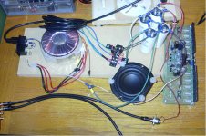
Joy at last!
You can't tell from the photo, but there is music coming from that little speaker! I built the second board exactly as the first. I was able to adjust the voltage drop across the 100R test resistors to 4.1V. Then I swapped out the test resistors for fuses, hooked up that speaker and gave it a signal.


 !
!
That means that I either fried a component, or make a soldering mistake with my first board. It may take a while to hunt it down. I've already replaced or checked several components. I just have to slog through it!
You can't tell from the photo, but there is music coming from that little speaker! I built the second board exactly as the first. I was able to adjust the voltage drop across the 100R test resistors to 4.1V. Then I swapped out the test resistors for fuses, hooked up that speaker and gave it a signal.
!That means that I either fried a component, or make a soldering mistake with my first board. It may take a while to hunt it down. I've already replaced or checked several components. I just have to slog through it!
Attachments
I am happy because of you Byron...finally you are listening some music
thank you as you have informed to us...also by the picture.
Here you have folks..something about the
MKIII Hx on board heatsinks thermal issue:
MKIII Hx vertical on board heatsinks issue. - YouTube
regards,
Carlos
thank you as you have informed to us...also by the picture.
Here you have folks..something about the
MKIII Hx on board heatsinks thermal issue:
MKIII Hx vertical on board heatsinks issue. - YouTube
regards,
Carlos
These hot transistors (CCS and VAS) can be installed directly into the main heatsink
below the board (beneath or under)... a small hole must be made to allow you to insert your screw driver to attach or detach these transistors..... you can use 1 inch and a half wire length and connect your transistor using a "transistor socket"...this way not so long wire will be soldered into the board copper side and the socket will allow you to connect and disconnect easy because board is mounted using spacers that produces a room (empty space or clearance beneath the board)...so you can insert the socket.
The other option is to increase heatsink. using a taller one, a bigger one.
The third option is to reduce the current, that 22 ohms (in the CCS transistor) resistance should be changed to 47 ohms in order to reduce the current.
Good luck folks.
regards,
Carlos
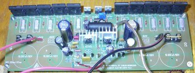
Byron, your picture in post 289 shows your amplifier without a heatsink for the output-transistors.
If you tested it like that, you really shouldn't.
Those output-transistors have very little capacity to get rid of heat on their own,
and your vbe-multiplier (thermal compensation) will not be thermally coupled to them.
Best regards,
Klaas
If you tested it like that, you really shouldn't.
Those output-transistors have very little capacity to get rid of heat on their own,
and your vbe-multiplier (thermal compensation) will not be thermally coupled to them.
Best regards,
Klaas
Cannonica,
Dats going to be pretty difficult considering the items being covered by the heat sink. Well unless we are talking 4 inchs of wire, would this be an issue with stability..? The way you are going you will have to make the tabs high enuf for clearance and servicability, you will still need 3-4 Inch leads@ a min.....
I like it , if the wire lenght is not an issue ...
I like your solution Cannonica
But keep wires as short as possible... 2 inches is fine... 3 inches is too much.
Having long wires you will have big inductances.... and will create a tuned circuit within the transistor operational range.... these MJE are high gain (250) and high frequency (more than 150 Megahertz).... long wires combined to circuit and wire capacitances may create a tuned frequency... an explosive combination that may drive the stage to oscillate.
Use sockets..there are fine sockets and keep wires short...install aerial (roof style alike Cannonica suggested) or bellow the pcboard..... anyway you do, try to keep wires short in lenght.
These two transistors will need insulators because they will share the same heatsink.... this will be good because the colector will not be connected to a big block of aluminium...colector is audio output lead and will send audio to a high gain (current gain) darlington output transistors....so..... even not having high gain of voltage (more sensitivity to noise pickup) it will have high current (can unstabilize too...not so hard as voltage gain but is problematic too.... gain there is 2500 or more... current gain).
Keep them at less than 52 degrees celsius..... excellent temperature is something alike human fever..... 40 or 41 degrees celsius... doing this way you will have long life to your circuit...will be there, playing nice sound to your sons and grandsons.
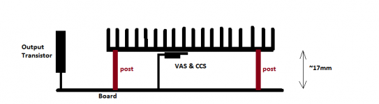
17 mm is wonderfull Cannonica.... really very good...will work perfectly.... use insulators to both transistors.
regards,
Carlos
But keep wires as short as possible... 2 inches is fine... 3 inches is too much.
Having long wires you will have big inductances.... and will create a tuned circuit within the transistor operational range.... these MJE are high gain (250) and high frequency (more than 150 Megahertz).... long wires combined to circuit and wire capacitances may create a tuned frequency... an explosive combination that may drive the stage to oscillate.
Use sockets..there are fine sockets and keep wires short...install aerial (roof style alike Cannonica suggested) or bellow the pcboard..... anyway you do, try to keep wires short in lenght.
These two transistors will need insulators because they will share the same heatsink.... this will be good because the colector will not be connected to a big block of aluminium...colector is audio output lead and will send audio to a high gain (current gain) darlington output transistors....so..... even not having high gain of voltage (more sensitivity to noise pickup) it will have high current (can unstabilize too...not so hard as voltage gain but is problematic too.... gain there is 2500 or more... current gain).
Keep them at less than 52 degrees celsius..... excellent temperature is something alike human fever..... 40 or 41 degrees celsius... doing this way you will have long life to your circuit...will be there, playing nice sound to your sons and grandsons.
17 mm is wonderfull Cannonica.... really very good...will work perfectly.... use insulators to both transistors.
regards,
Carlos
Cannonica,
Dats going to be pretty difficult considering the items being covered by the heat sink. Well unless we are talking 4 inchs of wire, would this be an issue with stability..? The way you are going you will have to make the tabs high enuf for clearance and servicability, you will still need 3-4 Inch leads@ a min.....
I like it , if the wire lenght is not an issue ...
A brick-like heat sink of 70mm x 45mm with fins as high as the cabinet permits. Raised 17mm above board surface. It should clear everything.
TO-220 sockets MAY be all that's required to raise the transistors to the correct height, furthermore, it will permit cliping-on the heatsink-transistor assembly. I said MAY because I haven't verified yet as I don't have those sockets handy.
Now the posts... where to attach them???...
Matched transistors and off set
The most important transistors to match are the input differential pair....usually when you have them matched in gain you will have small off set (1 to 10 mV....maximum acceptable (bureaucratic rule) is 25mV)....BUT...this will happens if you have drivers matched and matched output transistors.
When you have NOT matched output and drivers....then you will have high off set anyway.... and because the units not matched...good when all them are matched.... despite this is difficult...hard to find matched parts....usually PNP have more gain than NPN.
A friend had 28 mV offset using matched transistors in the differential pair (PNP units)..... BUT, his drivers where not matched, one was 117 and the other 65.... so...he still had 28mV off set DESPITE using matched differential pairs...... and the reason why was the unmatched drivers and output.
So, the clever man from Greece, decided to change their differential as he had not matched drivers...he used different gain in these differential in order to match the global amplifier....he had 1 mV off set and also he could have the same current in the output... in the PNP emitter resistances and also same current in the NPN transistors emitter resistances.
So.... the unmatch in the differential produced a global match..compensated the drivers this way..unmatching he compensated the drivers.
All this is just our fanatic need to have things perfect in an unperfect world, with non perfect ears and non perfect acoustic environment and non perfect speakers..... our fanatism drives us to worry about things that are not that important....small off set represents nothing or half of anything...does not harm sonics, does not impair audio quality, does not bother the output transistors..... and represents a very small waste of energy..something not important...but to the fanatics (WE)...here is the Greek man experience that may help you if you want if perfect.
Perfection is an unreachable dream..... but if you want this....enjoy and be happy.
There are other methods to reduce off set...but really i will not explain because this is not that important.
regards,
Carlos
I think you are attributing the output offset error to the wrong end of the amplifier.
The output stage is inside the DC and AC feedback loop.
The gain of the amplifier combined with the NFB automatically reduces global errors for output stage imbalance.
The front end determines the output offset unless there is a gross error in components later in the amplifier.
Half of the front end is not inside the NFB loop. NFB cannot automatically reduce errors in the two halves. A mismatch between the half inside the loop and the half outside the loop cannot be corrected/reduced by using amplifier gain.
Look at D.Self's explanation of what happens to offset and front end voltages when deliberately different transistors are used for the LTP pair.
Adjusting to front end to bring the front end more into balance is the correct way to reduce errors.
Adjusting the front end to send it more out of balance to correct errors later in the amplifier can never be the correct way to set up an amplifier.
I think this is where our views differ.
The data available to the "clever man in Greece" is not available to me.
I cannot tell whether he brought the front end into better balance and thus reduced the errors or as you claim pushed the front end out of balance to compensate another error with a second error.
Last edited:
- Status
- Not open for further replies.
- Home
- Amplifiers
- Solid State
- Dx Blame MKIII-Hx - Builder's thread