
 Hi guys I been doing mister Alex MM layout for the future, I decide create a similar one like his board, but this is a "fanatic motivation for me",probably someone is going to complain or else but this is a way to help in some way, Alex MM board is unique, and I'm not trying to let him down, just to share ideas that is all, is someone like this idea I be happy to share to you guys is in Sprint Layout 5 format, so Carlos already told me it will be a waste of time if I don't share, this is vargasmongo a humble electronics enthusiast from Puerto Rico with lot of respect to you guys. I apologies in advance if my English is terrible.
 regards
vargasmongo
Last edited:
View attachment 246018 Hi guys I been doing mister Alex MM layout for the future, I decide create a similar one like his board, but this is a "fanatic motivation for me",probably someone is going to complain or else but this is a way to help in some way, Alex MM board is unique, and I'm not trying to let him down, just to share ideas that is all, is someone like this idea I be happy to share to you guys is in Sprint Layout 5 format, so Carlos already told me it will be a waste of time if I don't share, this is vargasmongo a humble electronics enthusiast from Puerto Rico with lot of respect to you guys. I apologies in advance if my English is terrible.
regards
vargasmongo
Nicely done Juan but I think it's better for you to remove that footprint of resistor (100R) in parallel with the fuses. Edit: and that 10R(input ground) resistor can be deleted too
")
Last edited:
Oh that can be change Junie no problem
Aha that is just a reference not need to be on the layout
thanks for the tip Junie
Nicely done Juan but I think it's better for you to remove that footprint of resistor (100R) in parallel with the fuses. Edit: and that 10R(input ground) resistor can be deleted too
Aha that is just a reference not need to be on the layout
thanks for the tip Junie
Aha that is just a reference not need to be on the layout
thanks for the tip Junie
Just I got to call my friend delete he will take care of it
Nice work Junie!
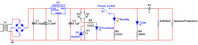
I plan on using a standby/power-on circuit. Here's the thing...
Juice will always be on this small circuit (I have a master switch embedded in the power inlet). The switch that will be at the front will power-on the softstart and the speaker protection at once. The overheat circuit will be part of it as well.
Your impressions?
Attachments
Question on grounding...
I know that bad grounding can lead to different, hard to explain noises and problems. I have a few questions that once answered can help me (and probably other as well) to better understand what can be done and what should be done.
I can identify many components that should be grounded, it means that they will all be correlated, but should they all be connected at a central point?
Here are the identified components:
- Power-entry ground;
- Chassis ground;
- DC "star" ground;
- Main transformer "Static shield";
- Speaker ground (negative lug);
- Audio-in ground.
From all of these, the only one that's clear to me is the audio-in ground, that's because I use the lifted ground.
But for the other ones; Power-entry ground, Chassis ground, DC ground, Main transformer "Static shield", Speaker ground, should they all be connected together in the middle of the "star"?
Should the power-entry modules's ground lug be connected directly to the chassis or to the middle of the star as well, on at the nearest poing from that lug?
It may be very basic questions to some, but to me it's not obvious.
Thanks for your precious inputs.
Martin.
Last edited:
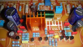
If it can be of any help, try photographing the solder side of the board. It's easier to find something wrong this way instead of looking with naked eye.
See the attached pictures, one is a the original framing at reduced resolution, the other is a crop at full resolution.... And one more to show my advancement. Still missing the small heatsinks. And I'll wail until the output transistors are screwed to the main heat sink before soldering the filter caps, for easier access.
Martin.
Hi, Martin,
Is that a ferrite core inductor in the output?
The Power entry third wire (PE=Protective Earth) must be permanently connected to the chassis.
We have been referring to this chassis connection as Safety Earth. This helps avoid confusion with all the other grounds in the equipment.
Note: permanent. That means it does not get dismantled to attach any other grounds to it. It should also be a mechanical fixing, welded (not soldered) or crimped.
Do you know the difference in meaning of welded and soldered?
There should be a copper wire/cable connection direct from that Safety Earth to PE. No other joint, nor component can be inserted into this PE to Safety Earth connection.
Hi, Martin,
Is that a ferrite core inductor in the output?
Yes it's a Bourns 2100HT-2R2-H-RC.
Thanks AndrewT. I plan on screwing-down the PE to the chassis then. And should the star-ground be connected to that "PE screw" as well?
Martin.
Yes it's a Bourns 2100HT-2R2-H-RC.
Thanks AndrewT. I plan on screwing-down the PE to the chassis then. And should the star-ground be connected to that "PE screw" as well?
Martin.
Thanks. But is it suitable for that purpose?
No.I plan on screwing-down the PE to the chassis then. And should the star-ground be connected to that "PE screw" as well?
Any extra connections to the chassis must not disturb the permanent PE to Safety Earth connection.
Is there a better way I can write that to get rid of ambiguity?
But to extend the explanation, you can add an extra connection above and separate from the PE to Safety Earth connection.
Use a longer bolt/screw than neccessary.
Nut and lock nut the Safety Earth tag/fixing.
Use the spare thread to add more nuts to secure an extra tag/s. These extra tags can be dismantled without interfering with the permanent PE to Safety Earth connection. I prefer a completely separate bolt/screw for the Main Audio Ground to chassis connection. It does not have to be near the mains incomer nor the Safety Earth bolt location. It must be capable of passing Fault Current to PE and survive long enough to blow the mains fuse and for the arc to extinguish.
Last edited:
Thanks. But is it suitable for that purpose?
Why not? it has correct inductance, high current capacity, low resistance and is documented as suitable to be used as an output choke. You think that not being an air-cored inductor can lead to problems?
Thanks AndrewT, it's not ambiguous anymore and it's gonna help me (us?) implement safe and efficient grounds.
Martin.
Yes....
Yes....
hmmm... can you explain what kind of problem this can lead to?
EDIT: Well, a quick search revealed this (below).... I didn't investigate into this before selecting the ferrite-core inductor I chose. I may replace it.
[wiki=(About air-cored coils)
Its inductance is unaffected by the current it carries. This contrasts with the situation with coils using ferromagnetic cores whose inductance tends to reach a peak at moderate field strengths before dropping towards zero as saturation approaches. Sometimes non-linearity in the magnetization curve can be tolerated; for example in switching converters. In circuits such as audio cross over networks in hi-fi speaker systems you must avoid distortion; then you need an air coil.]%[/wiki]
Last edited:
- Status
- Not open for further replies.
- Home
- Amplifiers
- Solid State
- Dx Blame MKIII-Hx - Builder's thread