The 100pf miller capacitor on the LTP current source is a true non-sense. It not only destroys CMRR of the LTP at high frequencies, but it also feds the ripple on the positive supply rail into the signal, and the higher the frequency the worse it becomes. If the amplifier ever oscillates, this capacitor will make it much worse..
I've seen this done too many times to count, "and for the life of me, I don't know the reason why...."
I have never seen miller capacitors used in current source transistors, it's pointless. The current source is no longer a current source, it becomes a capacitance multiplier, it acts like a much higher value capacitor connected directly from the emitters of the LTP to the supply rail...
I have never seen miller capacitors used in current source transistors, it's pointless. The current source is no longer a current source, it becomes a capacitance multiplier, it acts like a much higher value capacitor connected directly from the emitters of the LTP to the supply rail...
Not at all.
Wether it s good or not, in this amp, it act as a low pass filter by
slightly reducing the bandwith of the differential.

It seems to me that it would have no effect on small-signal bandwidth, even if it were increased to e.g. 1uF. Distortion may be worse, though...

Build and check your theories fellows...there are enormous gap between theories and
reality.... if half of the energy you spend thinking was used building, you would have confirmations and dennies about your thougths.
I am still trying.... at least three hours a day in the workbench trying something.
People that has built do not want to give up, they want to keep the amplifier because nothing they have heard sounded so good.... and i agree with that.
The amplifier is unconditionally stable in simulators, also can play for monthes as my computer monitoring unit did....but could not resist to high frequencies, high level steady tones entering.... and intermittent (periodical) , this means, sometimes the problems happens, sometimes not.. the most hard trouble to debug.... when happens burns fuse and you cannot inspect anymore.
This (high level of high frequencies) are not something you find, easy, or usually, in musical programs, in recordings we use.... only in high end recordings... also microphonic feedback sounds are not something we will face....but happens, and amplifiers have to.... must to face all these things and continue stable.
C18 removal, also the 470pf removal really turns the amplifier much more stable....but problem is sound reproduction quality, as this way the amplifier turns something average in quality (medíocre)..nothing special, very common, standard...alike thousand of others, without that live emotion.
There's no other way to understand what i mean but building and listening by yourselves.... the ones have built, despite knowing they can face problems, do to even accept the possibility to give up... and only these guys can really evaluate as they are listening.
The difference is huge...this amplifier sounds alike a modern amplifiers, a modern audio system compared to a stylus/diafragm/horn old phonograph... in the very first moment you listen you feel enormous difference...ask the ones have built.
I have compared yesterday.... daugther was here and asked me to put the Blame back in place.
Will try to protect VAS, also will increase the output transistors quality to see if they can face overdrive with square waves and high frequencies...and using an unstabilizing output load.
Do not be sad friends, i am still working..for a while i have removed the "guarantee" of reliability for the present schematic, but one day i will find a good solution, keeping the extraordinary unbeatable sonics and offering you a more safe amplifier.
Users are saying it is safe...they are listening daily and had not problems.... well..they have not faced, yet, the conditions that unstabilize the unit.
I have tried Marcisium Laboratories 24 dB active filter..increasing treble level fuses blow, and monitoring using scope...i have just reached the power limit, was not and overdrive.
I continue in the struggle to offer to builders and to my dear friends, an unconditionally stable amplifier, not only in the simulator but real life too.
The "avant premiere" version is unconditionally stable...but sonics is average, one more common things..compared to the previous, the thread official amplifier, the "avant premiére" is a junk.
Funky2x have faced several toubles..ask him if he want to give up from this amplifier....ask Luka, or the others have build...no one accept this possibility...they said will fix if something burns but will be using it as it is unbeatable.
I am trying all i know and suggestions from Wahab, from kind Eva and from others... also trying some combinations of these ideas.... the only one worked was the "avant premiere"..but sound quality resulted very poor, very common, average, mediocre, standard as thousands of amplifiers you find...nothing special or astounding.... the unit became without live performance.
I am not sad, not depressive, not ashamed...i have made what is honest, correct and decent to do, to say the truth... respecting forum builders.... i am feeling good that i could do that.... i my mum was alive she would smile and would say, as she usually said....you are a real man Carlos!
You should try to produce our own designs and offer them to forum, instead to go "evaluating" other guys work... this is less productive and needs much less courage, as you can criticize others, and this is easy, while nothing from you was offered to criticism. In my point of view, this practice does not help anyone except your own ego.....you see your threories proved in real life, as i have tried them, have not worked....or have worked to produce an average amplifier.... this i not evolution...this is to maintain the "status quo"... repeating old practices, V/I limiters, or slowing down amplifiers...doing what others have done....nothing new or creative..just text book talking parrots some of you (only three or four of you)
regards,
Carlos
Last edited:
Fixed!...now rock stable...Guaranteed@.... Build it!
Builders...now you know how to stabilize.... thank you WAHAB and thank you KLACHKISTE by your cooperation.
I do not know about sonics..will test this latter.
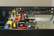
The shield is a piece of food can... something that have iron....soldera wire on the blade and run it to the ground...you can insulate the blade, painting or covering with some plastic foil...glue it to make a shield, a wall, a barrier between the output coil and the input circuit.
The image show you what to do..... all informed there.
Be happy.... i hope sonics will be good..... i do not know...doing other things this morning.
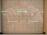
Image shows 25 Kilohertz waveform with 7 ohms inductive resistance as a load... square wave entered.... full power, below the clipping naturally...but can clip without problems....tested till 100 kilohertz and several volts have entered..rock stable...not dangerous anymore.
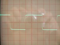
Other image, is 20 Kilohertz with 2.2 uf in parallel with the 7 ohms inductive resistance... square wave entering, and below the clipping threshold naturally...almost full power.
regards,
Carlos
Builders...now you know how to stabilize.... thank you WAHAB and thank you KLACHKISTE by your cooperation.
I do not know about sonics..will test this latter.
The shield is a piece of food can... something that have iron....soldera wire on the blade and run it to the ground...you can insulate the blade, painting or covering with some plastic foil...glue it to make a shield, a wall, a barrier between the output coil and the input circuit.
The image show you what to do..... all informed there.
Be happy.... i hope sonics will be good..... i do not know...doing other things this morning.
Image shows 25 Kilohertz waveform with 7 ohms inductive resistance as a load... square wave entered.... full power, below the clipping naturally...but can clip without problems....tested till 100 kilohertz and several volts have entered..rock stable...not dangerous anymore.
Other image, is 20 Kilohertz with 2.2 uf in parallel with the 7 ohms inductive resistance... square wave entering, and below the clipping threshold naturally...almost full power.
regards,
Carlos
An externally hosted image should be here but it was not working when we last tested it.
Attachments

It is all rigth about sonics..... small losses, as i am not using 33pf miller at Q7
Some other minor modifications helped, also bypass in the input condensers,bypass in the VBE multiplier transistor....some small change, 22uf plus 100N.... input had 2.2u in parallel with the input electrolic....
Bass is fine...also speed and dinamics.... i have perceived some small difference in high mids and treble...but something to pay by the stability.
Builders should make these modifications, at least in one channel as i did for comparison.
Be happy..... at least the way i am.
regards,
Carlos
Attachments
Last edited:
Well boys, i understand you feel shocked, something seems to be a scandall
things looks unobtanium, wrong placed, bull sheep, foolish, vodoo, big magic, a lyer movement, unobtanium, inexistium...and so on.
You should understand, if you want naturally, because if your decision is not to understand, then do not waste your time reading...will be useless.
Observe that things have a sequence, the miller, or alike Miller in the CCS is not a miller, it is there to present a capacitance between two potencial, there are differences in voltage, this creates flow...and flow of electrons also absorb unstabilities... AC flow in this case.
In the sequence of debugging..when i had unstabilities first time... a long time ago, down the last Christmas times... then i was trying things in sequence...one before the other you understood...so... maybe the small capacitor in the CCS was the first in the sequence...each capacitor changed, or replaced, or introduced, produced some result in the scope...so...they were added one followed by another one, the next one..all in sequence...one each time...and of course this is a system...all them work together..maybe the third or fourth introduced capacitor, or fourth change, or modification, turn the first one not needed anymore...so, something, some part, actually may be doing anything there....because the sequence..i was introducing parts till i found amplifier more stable... or less unstable (monthes ago)...and i have not removed the fourth one when installing the fifth one...do you understood..there is a sequence and mathematic combination of things.
So, if something seems wrong...do not use what you feel is wrong folks!....build the amplifier and just do not use things you do not believe..or try Doctor Self original schematic..you do not want to buy the idea to build my amplifier, also you do not want to build the way i did.... do whatever you want..but do something in the place to only talk and give notes to other folks work.... do something!
So, instead to be producing analisis, simulations, consulting books or theories.... solder two leads of a capacitor into an amplifier, connect scope, audio generator, load in the output and check if do nothing...after that, take not your thougths and do it while listening music...now you did the rigth thing, and will learn a lot.
regards,
Carlos
Last edited:
Todd Johnson is busy, next month he may have some time to help me
Then we gonna have updated schematic, including the modifications, and a new thread will be opened to the Dx Blame ST.
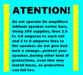
Do not give bad luck a chance..use fuses in series with your speakers!
regards,
Carlos
Then we gonna have updated schematic, including the modifications, and a new thread will be opened to the Dx Blame ST.
Do not give bad luck a chance..use fuses in series with your speakers!
regards,
Carlos
Attachments
Better sound, or almost the same sonics, you should build almost the same
Maybe some different currents, other transistors and different feedback, more current to the drivers, more voltage in the supply.
Really folks, i am sorry, this is the only way.
Blameless marriage with Hugh Dean ideas resulted perfect...my contribution, my hard work, made the hell thing work stable..... was not easy to do that.
Remember always... behind me, the inspiration, is Hugh Dean and Douglas Self.... if your trow stones on me, are trowing stones in those fellows too.
Enjoy...my hands are burned, i am tired..but was good to make it stable.
regards,
Carlos
YouTube - Dx Blame ST.mpg
According to the waveforms and their description in post 866, the amplifier still exhibits overshoot and slight ringing when driving a resistive load, which is the consequence of a too small phase margin. The ringing frequency is where open loop gain mets closed loop gain.
Enjoy the best amplifier ever made!
Build the ST (Stable) amplifier...the unit survived to 20, 25 and 30 Khz, full power, square wave, into a 7 ohms inductive load and in parallel a capacitor... 2.1 microfarads measured.
This use to unstabilize amplifiers and mess with the waveform... the effect in the Dx Blame ST waveform was not so big as many other "said" professional amplifiers.
Enjoy the lovely sonics, the perfection in the dinamics and excellence in sound stage.... lovely high frequencies filled with brigth and presence, deep present bass, room shacking one.
Do not build if you have another amplifier that was expensive.... it will be beated, smashed and exposed to shame when compared with this one!
Competition is nervous, filled with envy...let them face the reality.
regards,
Carlos
Attachments
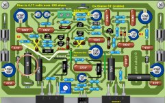
Update is in post 866, the artistic image has some new values, parts to be removed
too.... the schematic is almost the same, exception are these parts.
New schematic will delay a lot, as Todd is really busy those days.
So, use the 866 image after assemble the amplifier, you will remove two capacitors and will substitute 2 resistance values and other small things...you can do that after construction following the schematic provided, version 1.3 and layout provided, version 1.4.... also the artistic view from Todd Johnson is very helpfull to assemble and to check parts.
I suggest you to build using the Dx Blame ES schematic and layouts...after finish, then you will remove some parts, will substitute one capacitor with a bigger one, or will solder 47pf bellow the board to increase the 82pf capacitor value,will solder a jumper in the input lift ground resistance, will produce a small shield or will remove the output inductor instead to use the shield, installing it in the output connector.... well.... the Dx Blame ST is almost the same amplifier...small modifications only.
I have not idea when we gonna have the St schematic...so..if you decide to wait, maybe will wait a week or several monthes.
Dx Blame ES boards are not modified, all modifications can be made in the same board...no special board..there's no copper track modifications.
regards,
Carlos
Attachments
Last edited:
Hello Meanman.... means remove the 18pf capacitor, C18
Not the condenser and nor the jumper...the white line is not a jumper, it is a metalic sheet, alike the ones you have in food can.... a shield, alike a magnetic wall to insulate magnetically the output coil that can send magnetic field to the input circuits..the big white line means the metalic shield that has a wire soldered to it, and the other wire extreme is connected to ground.
The metal shield must be glued into the board, positioned alike a wall, and the metal must be insulated using plastic tape, paint or other idea you may have.
Other thing you can do, not to use the shield, the metalic piece of steel..is to remove the output coil, also the 10 ohms resistance associated, and install them in the output connector..the place you connect your speaker wires..this way you do not need to use the metalic barrier..the shield (idea from Andrew T)
regards,
Carlos
......................
Hello Pocoyo!
.......................
I think we can install the zobel filter in the speaker output jack too.
This will avoid you to use the shield, also we gonna avoid all that crowdy part in the board too.
But i have not tested the zobel out from the board...seems to me will work fine...but, it is not bothering, as it is in the low sensitivity board side...when the output coil is in a very dangerous position.
regards,
Carlos
regards,
Carlos
- Status
- This old topic is closed. If you want to reopen this topic, contact a moderator using the "Report Post" button.
- Home
- Amplifiers
- Solid State
- Dx Blame ES .... based into the Blameless, i am trying a new amplifier