What about installing the output in the middle of the PCB?, because there is a big track there, just where you wrote "remove this one" in yellow letters. This way we respect simetry and a certain distance between power rails, input section, output devices, and we can instal the zobel on the speaker's binding posts...just a couple of holes with a Dremel ")
Hi, sorry to hear the troubles
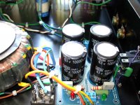
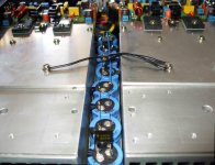
In this Dx layout I have tried to "reverse" output transistors, just to see what happened
Note that board is mounted flat on heatsink, upside down
Should fit a relatively cheap 80mm box height
Wires from supply to amp board are straight and very short
But I have had enough layout headackes even with the much simpler Dx
Attachments

According to the waveforms and their description in post 866, the amplifier still exhibits overshoot and slight ringing when driving a resistive load, which is the consequence of a too small phase margin. The ringing frequency is where open loop gain meets closed loop gain.
I think he may have the images reversed. The one with the overshoot is probably the resistor in parallel with the 2uf cap. The output inductor will cause that to ring, even if the waveform on the other side of the inductor is perfectly square.
If it were ringing that bad into just a resistor with a large signal input, it would sound terrible. I've heard (and built) marginally stable amps that sounded IN YOUR FACE BRIGHT and didn't ring that much into just a resistor. And the ringing frequency was a lot higher.
Wg_sky, this amplifier is the best i have ever listened.
With ringing or without ringing it sounds lovely, almost perfect..the advantage compared with others is huge.
Of course the ringing image is the capacitor result... and this is not an usual load to power amplifiers...so, this was made to check stability, to know how much stable or how much stable it is...i have no intention to use the capacitor together my amplifiers, so, i suppose the ringing will not always be present in audio reproduction... at least, i hope so.
Waveforms, simulator results, cannot offer you a perfect idea about sonics.... my old Dx amplifier shows almost the same results watching the scope, and simulations are also not too much different, but sound quality difference is huge.... human ears, human perception, is another story.
Dx amplifier has a lot of bass when connected to real speakers, the Dx Blame ES and the ST has a lot of treble when connected to real speakers, both are electrically flat and also flat in the simulators..this shows how real things are different from theories.
This circuit is almost entirelly made by Doctor Self, the input is from Blameless and the output is also something doctor Self have used in other amplifiers.
Usually, with some very honorable exceptions, Doctor Self know much more than we know, he use to be our teacher, not the opposite.
regards,
Carlos
Last edited:
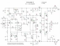
Soundbuster have prepared a provisory schematic
this one include the minor modifications, so, it is the Dx Blame ST schematic, the stable one.
This will help you, an interim schematic while Taj is busy.
Not to complicate things...build exactly as the Dx Blame ES schematic, use the artistic view to check your construction...then, replace rail resistances by 56 ohms or 68 ohms (R17 and R22), increase Miller capacitor, from 82pf to 120 pf, or install a 47pf unit in parallel with the 82pf (C13) capacitor, remove C11 and substitute C25 by a 10pf unit, use wire jumper and short R3.
Remove output coil and zobel filter and install them in the speaker output connector, or install the shield as posted, and explained previously.
Increase your stand by bias to 4.7 to 5.5 volts and enjoy the lovely sound from this, almost perfect, audio amplifier.
regards,
Carlos
Attachments
All you need to know about Dx amplifiers are in threads opened for this purpose
Dx amplifier thread,
Dx Precision 1
Dx HRII
Dx Trust
Dx DHR Turbo
Dx Blame ES (this thread)
All schematics, layouts, adjustment instructions and so on are in Greg Erskine home pages:
Greg's Web Site
Osciloscope paterns usually are not provided, as Dx amplifiers performs better while listening than measuring...despite they measure good too (just an accident, this does not means guarantee of good sonics)
regards,
Carlos
comparison between Dx Blame ES, or ST, with the Dx Amplifier, the standard one
Is the same when you compare this car with a VOLKSWAGEN beetle:
http://www.youtube.com/watch?v=TC2FJ4Mbg1I&feature=grec
Is the same when you compare this car with a VOLKSWAGEN beetle:
http://www.youtube.com/watch?v=TC2FJ4Mbg1I&feature=grec
It depends which beetle. heheIs the same when you compare this car with a VOLKSWAGEN beetle:
YouTube - BMW M5 V10 Hurricane G-Power
(sorry for OT
)Attachments


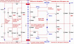
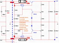
Dx Corporation Voltage regulator, an electronic, adjustable, voltage stabilizer
Made to my needs, but can be used as a Workbench regulator, and can be used with several amplifiers..input voltage to the electronic stabilizer circuit (with error amplifier) can go from 48 to 64 Volts.
This was made to the ones (me!) have only a single power transformer and want to use it, connecting to two Dx Blame ES, or ST, or Dx Amplifiers, or HRII or any other amplifier you want....but having not interaction of voltage drops between these 2 stereo amplifier channels
This way, i am using a single transformer, a single 10 amperes (minimum) rectifier bridge or discrete diodes connected in bridge mode, and a single bank of condenser to face 5 plus 5 amperes (each rail power drain).
This was calculated to 35 plus 35 volts, and 2.5 amperes each rail...so.... i will use 2 (two) electronic voltage regulators, despite you see only one in the schematic rigth size referenced by the vertical blue dotted line.
The voltage drop is 100 milivolts when power amplifier will working full power (undistorted) and can face clipped signals till 3.5 amperes without big losses, big drop of voltage...this keeps voltage stabilized in the output despite other channel variations of current drain..... it is the way i found to use a single transformer, a single condensers bank, and them to have stable supply without any interaction in between these two channels used in a stereo amplifier.
Is this better than 2 transformers, two rectifiers and 2 condensers banks....i think it is not better, also voltage regulators must be very fast, as power amplifiers in the microsecond one may have 100 miliamps and then in the microsecond may have 2.5 amperes each rail.... electronic supply must be fast enougth to follow these fast variations, so, they must be so fast as the amplifier, and better if electronic supplies be faster than the audio ... amplifier.... as my voltage regulator is not faster than the power amplifier current drain variations, then i am using another electrolitic condenser bank to supply electrons while the voltage regulator will be thinking "what to do next".... the electrolitic, in the output, will do the job while the electronic regulator will be thinking.
This is some sophistication that some folks loves, other hates, works fine, i have made hundreds and were applied to Radio Amateurs, when their transceivers jump the consumption from 500 miliamperes to 30 amperes in microseconds when transmitting in USB mode.
Heatsink size, series transistors pass transistors quality, will variate depending your input voltage (in my case 48 Volts) voltage and current consumption...so...it is shown to 3 Dx Blame ST and using 48 volts in the input ...... other cases may be studied if you need.
Audio was recorded, in English and in Portuguese, explaining with more details the subject....30 minutes of MP3 audio recording, 15 minutes to each language...if you need, then write to uncle Charlie:
carlos.eugenio1951@yahoo.com
Todd Johnson is beeing invited to produce boards...of course others can cooperate too, but Taj boards will be official unless he decline to do the job.
Board wanted!..board layout wanted.... a single board, having two rectifiers, two voltage banks ( i will, personally use a single one) and two simetrical voltage regulators.... the smallest possible please..the condensers are already big enougth..but may left room to bigger condensers, because people may need to install higher input voltage, needing high insulating voltage condensers, that usually are bigger in diameter.
Series pass transistors can be any power transistor able to face 64 volts and 10 amperes, also other transistors can be replaced too..zener is 1 watt and resistances are 500 miliwatts or more...capacitor insulating voltage will depends your input voltage selected.
Is this better than the traditional, common and standard supplies?
I do not think so, it is an interesting resource to use in several amplifiers, also to you to "feel" that difference, can be very helpfull, but it is complicated and expensive.... serves when you have NO 2 transformers to use.
regards,
Carlos
Attachments
For safety reasons, install fast blow fuses before the series power transistors
So, exceeding the transistor safe limits, then the fuse will blow and no more excess of voltage will go to the power amplifier.
Attention, the Dx Blame ES and Dx Blame ST (they are almost the same) have the output fuse in the schematic, but have not the output fuse in the board...it is needed.... because amplifier failure will send rail voltage to the output, and this will go to the speaker and may burn the speaker..so, use, always, a fuse for speakers.
Install a fuse in the power output, in series with the speaker, 5 amperes, fast blow is fine.
regards,
Carlos
Attachments
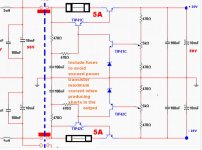

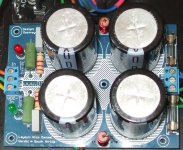
Dx Blame ST output fuses
Use 2.5A slow blow to 8 ohms loads...or 3.0A fast blow fuses.
Use 5.0A slow blow to 4 ohms loads...or 6.0A fast blow fuses.
This is when using 35 volts supply...other voltages must recalculate.
regards,
Carlos
Use 2.5A slow blow to 8 ohms loads...or 3.0A fast blow fuses.
Use 5.0A slow blow to 4 ohms loads...or 6.0A fast blow fuses.
This is when using 35 volts supply...other voltages must recalculate.
regards,
Carlos
Attachments
Last edited:
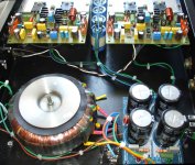
Dx regulator with fuse position fixed.
Transformer primary also has a fuse.
The power amplifier has fuses to protect the power amplifier.
Also the Dx Supply has fuses.... electrolitic condensers can short, then fuses blow... if mains fuse does not open in advance.
Do not forget fuses to the speaker output
Carlos
Transformer primary also has a fuse.
The power amplifier has fuses to protect the power amplifier.
Also the Dx Supply has fuses.... electrolitic condensers can short, then fuses blow... if mains fuse does not open in advance.
Do not forget fuses to the speaker output
Carlos
Attachments
Last edited:
- Status
- This old topic is closed. If you want to reopen this topic, contact a moderator using the "Report Post" button.
- Home
- Amplifiers
- Solid State
- Dx Blame ES .... based into the Blameless, i am trying a new amplifier