If smaller is needed, you can also try HS105-ND. I will use this.
Digi-Key - HS105-ND (Manufacturer - 577002B00000G)
Digi-Key - HS106-ND (Manufacturer - 577102B00000G)
An externally hosted image should be here but it was not working when we last tested it.
Digi-Key - HS105-ND (Manufacturer - 577002B00000G)
An externally hosted image should be here but it was not working when we last tested it.
Digi-Key - HS106-ND (Manufacturer - 577102B00000G)
Do you know about Stradivarius, the best Violin ever made
When a Stradivarius violin is playing, their
sound characteristics are perceived by
experts ... if the sound is reproduced by
audio amplifiers, then, a few will
realize that the Stradivarius is playing.
Using the Blame Dx ES, you increase, and much, their
likely to perceive the excellence of sonics of a
stradivarius violin.
Give yourself a chance to hear one of the best
amplifiers ever created .... the Dx Blame ES
Use pcboard layout from Taj... respect values
printed in the schematic.. then you will
have a close encounter with paradise sonics
A divine amplifier.
Attachments
Last edited:
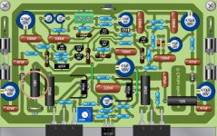
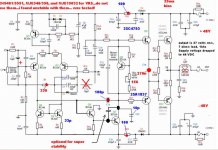
Here is the final schematic posted once more.
Also pcboard layout in Ray X vision style
Also copper tracks to toner image transference and other to photo chemical
If you need a very high resolution Image, just mail me, i have a 5.3 Megabytes image that you can zoom a lot without edging defects appear.
You can have this, and much more, in the Greg Erskine (Gerskine) home pages, the ones dedicated to the Dx Amplifiers:
Greg's Web Site
Adjustment instructions can be found in Greg Erskine pages.... what are you waiting for?... give yourself a chance to listen to the best wide world audio amplifier (at least i could not listen anyone better those last 50 years)
regards,
Carlos
Attachments
Dear brother, Carlos!
You brought me to a difficult situation.
Another project, which must be built.
While the depression and lack of money paralyses me.
But no worries, as usual.
Dear grandfather always said:
It will not be this even so, just this little bit of good must be pass away, which now is!
So, please send me the high resolution picture!
Gyuri
It is good to know this Gyuri...also that depression is turning things more difficult
Because your satisfaction will be even bigger with the amplifier sonics results.... with sacrifices, the prize use to be bigger and better.
I am also broken...without money....if i had not friends to send me boxes filled with parts, i would have stopped my electronics activities since 2005.
Today i will dedicate to the 28 march release amplifier....maybe will be the same amplifier..without changes, as the input impedance failed (sound was not good)..i will try another compensation, another idea, from a German friend... will increase supply voltage, maybe to 64 volts...some transistors will be changed... capacitors too, will try to reduce the gain a little...and other attempts to make it better.... sonics will be the judge..scope will be monitoring to tell me if i made mistakes.... in a matter of 5 hours i will have a new amplifier.
But will not make any modifications that can kill the lovely boards Taj made...same board!....but more added transistors will be needed, as i have not release the DID (Dx insertion delay) nor the DSP (Dx safe protector) then i will have to increase transistors pair quantity to make it reliable.
I am waiting the sun to be higher in the skies to remove excesses of ligth from my workbench to start to work... a non stop work till good results or till give up to change things.
Send me emails, then i will have your adresses to upload the high resolution image.... it seems to be for toner transference, not to optical chemical method...well.... you can make the negative using ACDSee image editor and other softwares if needed.
I am happy today...my friend Luka, form Polland, will drill his heatsinks today.
regards,
Carlos
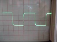
AVANT PREMIÈRE.... not the final one..but what i have made today
Maybe, something alike will be released march,28..... i am not sure..quality is not the same compared to the design offered..BUT, this one is much more stable... sound is not that good.... a very normal amplifier, without nothing very special, just the superb stability.
Removing the 33pf capacitor you have in the second VAS, from base to colector..then your sound is much better..but high levels of square wave, near the saturation, near the maximum..shows some small oscilations superimposed to the horizontal portion, the DC portion you have in the square wave....better sound without the 32pf miller capacitor to the second VAS (BD139)
To be continued next post:
regards,
Carlos
Attachments
Sound is excelent, but it is not so good as the 35V version
But it is much more stable..... to the ones loves measurements, then this one is better...to the ones loves awsome sonics, then use the 35V version.
Differential VBE voltages 585mV
First VAS and second VAS VBE voltage is 620mV
Drivers measure 560mV of VBE
Output measured 510 milivolts of VBE
Off set is 8 mV
bias adjusted to 25mA
Voltage drop in the rail resistances is 1.5 volts
Voltage between R14 and R15, measure do ground is 23.9V
Supply voltage, unloaded is 48.7V
Supply voltage full power, 7 ohms load, is 44V
Output is 27 VAS RMS, over 7 ohms loads, 60 Hertz, sinusoidal unclipped
I have used 2SC4793 and 2SA1837 as drivers...my intention was to increase supply voltage to 60 volts..... i will remove them..not needed with this supply voltage.
Bias trimpot was adjusted to 156 ohms
I am not sure if this one will be approved, but it is another option, for more stability.
Thanks to Krachkiste.... really the remotion of C11 (18pf) resulted good... a big surprise to me..thank you Kraschkiste.
I will be listening and testing next two days..then i will tweak for sonics once more... today i have tried stability and more power only.
It may reach 200 watts in 4 ohms..unclipped.
No!... i have not simulated this one.... had not time to do that.
regards,
Carlos

Apply the three steps to see if you like the sonics.
It is good that you have one working stable, so, you will be able to compare and to confirm what i have perceived too.
First remove C18.... having good result stop there.
No good result?.... then remove C25...... having good result stop after this removal.
Still having troubles?..... then include 27pf, or 32pf, or 33pf, or 47pf in Q7... connect from base to colector.
And give me your feedback about.... also compare sonics.
I found the sound resulted not fine doing these three steps...... the third step is the worse one.
Audio quality, in my point of view is 98 with the standard schematic....... 93 removing C18 only..... 86 removing C18 and C25.... and dropped to 80 when doing these three modifications together.
In other words..audio quality goes to the same Dx Amplifier, the Dx Standard level of quality.... a good amplifier, something no one will be ashamed compared to others, but will not the awsome, astounding, incredible anymore.
I will revert my monitoring amplifier to the standard, official schematic, today.
Mine worked without these bias fluctuations...maybe you have something wrong, something you could not find yet...let's see these super stabilizing modifications will help you.
Will look forward for your thougths about.
By the way, dear funky... these 33 volts appear in both rails?..... this means 330mA...so, a class A amplifier....how is the sonics when this happens..what you perceive in the sound reproduction......no!...i am not saying you not to try to find errors and to fix them....but we can learn something from these things happens..how is the sonics when you have this bias increasing... that seems to me oscilations... how sound these oscilations?...of course works very hot this way.... 11 watts each rail... 22 watts of heat...so, alike several JLH amplifiers.... good to cook eggs this way...i hope your heatsinks are big enougth, or you will loose output transistors because overheat.
regards,
Carlos
Last edited:
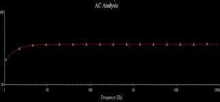
Interesting.... this "avant première" unit, is perfect in the simulator
Distortion is the lowest i could find.... or one of the lowest ones.... terrible flat...absolutelly flat...losses only below 5 hertz, waveform perfect...fourier perfect, harmonic distribution lovely...but this one is stucked in the bass...has no dinamics.... a hell thing... unbeliavable!... modifications are very small, and all them for stability.
Once, a good man told me the excelent amplifiers are the ones operates in the threshold of unstability.... i found that nonsense...but now a days, almost 5 years latter, i am realising that good man was rigth.
Will try something in between.... to see the result...not absolutelly stable, and not showing easy signs of unstabilities....maybe i am very wrong, i use to put my finger in the input, and i do all i can to listen a pure 60 hertz tone (my mains frequency)....but maybe if i listen some "chirps", or beatings, or nearby broadcasting radios may be a good idea.
Well... i will be sure about that.... and today... as i hate these doubts.
regards,
Carlos
Attachments
Last edited:
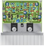
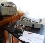
Powering up my "Lilly-board",
which is of course one channel of my BlameES.
I am sorry not to have the time I need to complete the amplifier faster.
I have to work very hard for my company right now.
So I do it slowly - beginning with the "Lilly-board"; the "Rachel-board" (right channel) will follow soon.
Powering on:
The PSU shows 38.2 V (without any load); two red LEDs saying: O.K.
After 5 seconds: the small green LED in Lilly's hair begins to shine, then: KLICK: the relay coil switches the relay's contacts.
The small speaker delay/protect circuit (in the front, below the power caps) works as designed.
So far - so good.
Maybe I have some time on the weekend and do a first test with a pair of Toshibas and a test heatsink.
Best regards - Rudi_Ratlos
which is of course one channel of my BlameES.
I am sorry not to have the time I need to complete the amplifier faster.
I have to work very hard for my company right now.
So I do it slowly - beginning with the "Lilly-board"; the "Rachel-board" (right channel) will follow soon.
Powering on:
An externally hosted image should be here but it was not working when we last tested it.
The PSU shows 38.2 V (without any load); two red LEDs saying: O.K.
After 5 seconds: the small green LED in Lilly's hair begins to shine, then: KLICK: the relay coil switches the relay's contacts.
The small speaker delay/protect circuit (in the front, below the power caps) works as designed.
So far - so good.
Maybe I have some time on the weekend and do a first test with a pair of Toshibas and a test heatsink.
Best regards - Rudi_Ratlos
hello all ")
Indeed the sound is excellent
precise and clean, and the bass is firm fast and present
It doesn't have that charm DXStandard has, but the sound is not
blurred and though better in my opinion.
I don't have a scope to measure the beast
Offset is ~5mv in one and ~6mv in the other channel
Biased to 5.2V on 100R (will have to fiddle a little with bias
to see what's going to happen)
Powered-up first time without smoke.
I thought it'll be tougher than DXStandard to put it together
but turnd out quite 'foolproof' with such a documentation
What are you waiting for folks!
Try it! It's not that hard believe me
and it's really worth it
luka
Last edited:
- Status
- This old topic is closed. If you want to reopen this topic, contact a moderator using the "Report Post" button.
- Home
- Amplifiers
- Solid State
- Dx Blame ES .... based into the Blameless, i am trying a new amplifier