Dear Taj wrote:
I have not tried that system so I can't comment about effectiveness/safety but remember to use warm water as recommended: you could experiment vertigo if you use cold water.")
He said this is not dangerous and really cleans well. The soap and warm water dissolve the wax and evacuate it.
I have not tried that system so I can't comment about effectiveness/safety but remember to use warm water as recommended: you could experiment vertigo if you use cold water.
I hope earthquake have not hitted you
You have faced a very strong one.....maybe the biggest one.
here is a fresh, brand new slide movie:
YouTube - March, days 03 and 04 pictures
set to 1080 for best image resolution
regards,
Carlos
You have faced a very strong one.....maybe the biggest one.
here is a fresh, brand new slide movie:
YouTube - March, days 03 and 04 pictures
set to 1080 for best image resolution
regards,
Carlos
I have adjusted two Dx Blame ES boards.
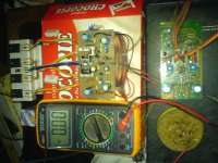
Attention!..... it is needed to run a wire from the transformer center tape and connect it to the heatsinks.... this kind of grounding is needed, in special if you're using high speed devices as i am using in my output (Sankens)
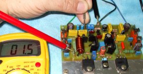
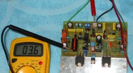
Three images will be posted, one is 3.6 milivolts, it is the off set...both amplifier had the same off set, same transistor stock.
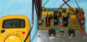
Other image show you something around 4.5 volts, i have adjusted this way, this measn 45 miliamperes of stand by current...both amplifiers were adjusted same way, VBE voltages in the power transistors is 565 milivolts.
The image measuring 1.5 volts alternated, is 60 hertz measurement when i touched the input, the 220 ohms resistance we have in the input...my body has captured 60 hertz from my home wiring, and i was transfering this signal to the power amplifier input..because of sensitivity very low, only 1.5 volts appeared in the output.
Tomorrow i will use scope and audio generator to inspect these amplifiers.
They are cool, stable, without too much big stand by current variation (only the normal when the amplifier gets warm)... no sign of unstabilities.
I have inverted drivers once again...the NPN was in the PNP place....i use to do that very often..be carefull, i hope you are more precise than uncle Charlie.
Also the VBE multiplier uses two resistances of 1K in series to create 2K unit....i have installed two units of 10K, total was 20K.
You see.... as i am this way, i believe some of you are this way too..check carefully, this amplifier works, and now a days we have 14 units working.
regards,
Carlos
Attention!..... it is needed to run a wire from the transformer center tape and connect it to the heatsinks.... this kind of grounding is needed, in special if you're using high speed devices as i am using in my output (Sankens)
Three images will be posted, one is 3.6 milivolts, it is the off set...both amplifier had the same off set, same transistor stock.
Other image show you something around 4.5 volts, i have adjusted this way, this measn 45 miliamperes of stand by current...both amplifiers were adjusted same way, VBE voltages in the power transistors is 565 milivolts.
The image measuring 1.5 volts alternated, is 60 hertz measurement when i touched the input, the 220 ohms resistance we have in the input...my body has captured 60 hertz from my home wiring, and i was transfering this signal to the power amplifier input..because of sensitivity very low, only 1.5 volts appeared in the output.
Tomorrow i will use scope and audio generator to inspect these amplifiers.
They are cool, stable, without too much big stand by current variation (only the normal when the amplifier gets warm)... no sign of unstabilities.
I have inverted drivers once again...the NPN was in the PNP place....i use to do that very often..be carefull, i hope you are more precise than uncle Charlie.
Also the VBE multiplier uses two resistances of 1K in series to create 2K unit....i have installed two units of 10K, total was 20K.
You see.... as i am this way, i believe some of you are this way too..check carefully, this amplifier works, and now a days we have 14 units working.
regards,
Carlos
Attachments
Last edited:
Member
Joined 2009
Paid Member
I have inverted drivers once again...the NPN was in the PNP place....i use to do that very often..be carefull, i hope you are more precise than uncle Charlie.
I did that too ! - my 2nd TGM build was producing a strange output and was drawing a lot of current (I used the resistor instead of fuse thank goodness).
The build is looking good Carlos.
I have faced several troubles...holes too much large to the track width...
some holes to component leads are cutting the track, interrupting electrically the track, if you do not melt a lot of solder, then the track goes interrupted.
Usually i invert.... i always did that Bigun.... maybe i have some short circuit inside my own brain, or worst damage..... almost 50 years building.... and BD139/140 are always with me, as they are very good (even to Radio Frequency transmitters too!).... even this way i continue to do those things.
Also i forgot what is always very needed, a mandatory thing, indispensable, that is to ground heatsinks and potentiometer cases..even if we are using metalic enclosures we have to run a wire from the star ground, the chassis ground or the transformer center tap ground to the heatsinks, all them, exception are the ones have "live" voltage as driver's heatsinks..also the potentiometers cases..back cases.
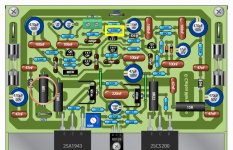
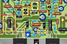
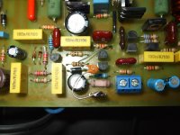
Then i had oscilations while i was testing a 220 ohms resistance in the place of the 470 ohms resistance...the gain one, in the schematic, it is marked inside yellow rectangle, up the image, near the ground spade.
When i have increased the gain (thinking about Rudi that has a low level pré amplifier output), and without the grounding, then i had oscilations, the zobel filter resistance overheated, and the zobel capacitor got warm (it is low reactance value to the frequency, not having resistance it does not overheat too much).... then i became worried, having concerns if my German friends have installed the ground wire to heatsink or not..... installing the wire, the grounding, the oscilation stopped...now i can put my finger in the input and clean 60 hertz from mains enters.
Well Bigun, you do not need these explanations, i am sure, but several beginners use to track my threads as i use to explain all i know.
People using wooden enclosure are searching for trouble, in special if they forget to do that.
The mains cable inside our walls, when passing current, produces electro magnetic waves that travells in the air and is captured by our body, we have iron in our blood red cells, also we have watter, and this constitutes an antenna, an aerial.... so, we behave alike a transducer, alike an antenna...electromagnetic waves crossing our body produces electricity, low level mains frequency, sinusoidal, signals...... when we touch the power amplifier input with our finger tips, or using metalic screwdrivers (watch screwdrivers, mini ones) them the signal is transfered and the amplifier works amplifying the mains frequency.... AC digital voltimeters can measure this frequency, in RMS and with a good precision.... so... we are alike a generator.
The level is very small, not the 1 volts the amplifier needs to produce 20 volts at the output spade....so..usally we have from 1 to 4 volts maximum.
regards,
Carlos
some holes to component leads are cutting the track, interrupting electrically the track, if you do not melt a lot of solder, then the track goes interrupted.
Usually i invert.... i always did that Bigun.... maybe i have some short circuit inside my own brain, or worst damage..... almost 50 years building.... and BD139/140 are always with me, as they are very good (even to Radio Frequency transmitters too!).... even this way i continue to do those things.
Also i forgot what is always very needed, a mandatory thing, indispensable, that is to ground heatsinks and potentiometer cases..even if we are using metalic enclosures we have to run a wire from the star ground, the chassis ground or the transformer center tap ground to the heatsinks, all them, exception are the ones have "live" voltage as driver's heatsinks..also the potentiometers cases..back cases.
Then i had oscilations while i was testing a 220 ohms resistance in the place of the 470 ohms resistance...the gain one, in the schematic, it is marked inside yellow rectangle, up the image, near the ground spade.
When i have increased the gain (thinking about Rudi that has a low level pré amplifier output), and without the grounding, then i had oscilations, the zobel filter resistance overheated, and the zobel capacitor got warm (it is low reactance value to the frequency, not having resistance it does not overheat too much).... then i became worried, having concerns if my German friends have installed the ground wire to heatsink or not..... installing the wire, the grounding, the oscilation stopped...now i can put my finger in the input and clean 60 hertz from mains enters.
Well Bigun, you do not need these explanations, i am sure, but several beginners use to track my threads as i use to explain all i know.
People using wooden enclosure are searching for trouble, in special if they forget to do that.
The mains cable inside our walls, when passing current, produces electro magnetic waves that travells in the air and is captured by our body, we have iron in our blood red cells, also we have watter, and this constitutes an antenna, an aerial.... so, we behave alike a transducer, alike an antenna...electromagnetic waves crossing our body produces electricity, low level mains frequency, sinusoidal, signals...... when we touch the power amplifier input with our finger tips, or using metalic screwdrivers (watch screwdrivers, mini ones) them the signal is transfered and the amplifier works amplifying the mains frequency.... AC digital voltimeters can measure this frequency, in RMS and with a good precision.... so... we are alike a generator.
The level is very small, not the 1 volts the amplifier needs to produce 20 volts at the output spade....so..usally we have from 1 to 4 volts maximum.
regards,
Carlos
Attachments
Last edited:
This is the first time i am building Dx Blame ES amplifiers using the official,
standard board size.
Taj has asked me if the board is fine...for sure it is....better than fine,
excelent...but buiding normal size, not enlarged, i have faced some
minor troubles.
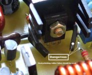
Drivers heatsinks must be distant from the board, not very good as they
can be more stable touching the ground surface, not stand up supported
by transistor leads...and to assemble them this way, then you will touch
a 2K7 resistance, the bootstrapp one, ... and this is dangerous....i have
soldered the resistance bellow the board because of that... this happened
to the NPN driver...... the other one, the PNP driver, also can touch, and
produce a short circuit with the heatsink...and these heatsinks are “hot”,
they have voltage, transistor has a conductive tab and the heatsink is
made of aluminium, not insulated, so...we have voltage there.
I found i have asked Taj to reduce small transistor track width..to avoid
short circuit while soldering, while melting solder this shorts the leads, even
with the leads so thin the way taj did (I have asked him to do this way).
My conclusion is the board is too much small.... really need 20 percent
enlargement.... distance from the bias trimpot and power transistor lead is
too much small too.
Also i found crowdy the left side... where you have the output inductor....
when the rigth side is almost empty...that emptyness bothers me.... i felt that
something was missed.... well.... Taj works a lot, also had parents and wife...
busy guy...i am glad he made all this lovely job, i am gratefull, but while building,
by the first time the board in the correct size, i realised that something can be
improved..... as we can short Q1,Q2,Q4 and Q5 because the board size.
For a while nothing will be fixed, but you should be aware of these details that will
help us, next time, to make a perfect board..as this one is almost perfect.
......................................................................................................
Here a high resolution video, pictures from the Dx Blame ES lovely boards...adjust youtube
resolution to 1080, click over the 360 or 480 and substitute by super high resolution:
YouTube - March, days 03 and 04 pictures
regards,
Carlos
standard board size.
Taj has asked me if the board is fine...for sure it is....better than fine,
excelent...but buiding normal size, not enlarged, i have faced some
minor troubles.
Drivers heatsinks must be distant from the board, not very good as they
can be more stable touching the ground surface, not stand up supported
by transistor leads...and to assemble them this way, then you will touch
a 2K7 resistance, the bootstrapp one, ... and this is dangerous....i have
soldered the resistance bellow the board because of that... this happened
to the NPN driver...... the other one, the PNP driver, also can touch, and
produce a short circuit with the heatsink...and these heatsinks are “hot”,
they have voltage, transistor has a conductive tab and the heatsink is
made of aluminium, not insulated, so...we have voltage there.
I found i have asked Taj to reduce small transistor track width..to avoid
short circuit while soldering, while melting solder this shorts the leads, even
with the leads so thin the way taj did (I have asked him to do this way).
My conclusion is the board is too much small.... really need 20 percent
enlargement.... distance from the bias trimpot and power transistor lead is
too much small too.
Also i found crowdy the left side... where you have the output inductor....
when the rigth side is almost empty...that emptyness bothers me.... i felt that
something was missed.... well.... Taj works a lot, also had parents and wife...
busy guy...i am glad he made all this lovely job, i am gratefull, but while building,
by the first time the board in the correct size, i realised that something can be
improved..... as we can short Q1,Q2,Q4 and Q5 because the board size.
For a while nothing will be fixed, but you should be aware of these details that will
help us, next time, to make a perfect board..as this one is almost perfect.
......................................................................................................
Here a high resolution video, pictures from the Dx Blame ES lovely boards...adjust youtube
resolution to 1080, click over the 360 or 480 and substitute by super high resolution:
YouTube - March, days 03 and 04 pictures
regards,
Carlos
Attachments
Last edited:
Always ground your heatsinks when building Dx Amplifiers
Guarantee will be void if you do not ground properly, i cannot take responsability when construction is not well made.
Even if you are using metalic case, metalic chassis, even if your heatsink is tigth fixed into the enclosure using screws..... even this way, run wires to the heatsinks, with inoxidable (or less subjected to oxidation) terminals and screw that into your heatsink.... do it for metalic, plastic case, fiberglass case or wooden case..always run a wire from the transformer center tap to the heatsink and potentiometers metalic back cap.
Metal chassis, when new, brand new units, are conductive in the points you drill holes to use bolts and nuts...but while time passes, the place produces rust, oxide, and this insulates or worse, behaves alike a resistance, sometimes a high value resistance, and in some cases behaves alike diodes.
Ground wires to chassis, better when soldered using high power solder iron, scratching metal surface and soldering there, a brigth solder..this is the best option...and run wires from this solder (chassis star ground) to your audio boards ground, also to heatsinks, potentiometer cases and to metalic shields used in high sensitivity amplifiers, alike phono pré amplifiers.
I am glad to know you are happy.
About MJE340/350, i have used and i dislike the units.
Was a problem when applied in the DHR Turbo, Dx Amplifier and Dx Blame ES..so, i think it is something to avoid.
Make a simple test..increase your bias turning the trimpot...it will increase till 28 volts over 100 ohms rail resistance... this means 280 miliamperes.
Now, try to reduce..... could you reduce to 4.5 volts again?
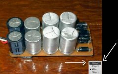
If you tried, and you bias drop down, then you are lucky with your MJE340/350 , as they have not created you troubles...but if you could not reduce, then remove these ones and install BD139/140....or, keep the MJE and install a 47pf capacitor this way shown.
Do not switch off the amplifier and wait condensers to discharge.... just increase to 28V and try to get back to 4.5 volts once again.
I use to test, almost everything people will try do to, all possible modifications, or the most "fashion" ones..for instance, to increase rail condenser values, these transistors and output ones.
Yesterday a friend come and said the amplifier was defective, he adjusted the trimpot and reached 28 volts..... and this is normal...we can misadjust too..we have range for that..but he felt defective because we could misadjust.
Other felt strange the bias current when the amplifier is cold and hot is different....but bias is different when cold and hot.... then i tested installing a soldering iron inside the heatsink to check..bias reduces (good, as this is his main task) when heatsink gets hot.....so...i am always observing these possibilities..and checking this continuously, because when someone comes to the thread and say that found something strange, i lost a lot of candidates to assemble.
I have tested this amplifier with several drivers, also MJE15032... i have also tried with 2SC5200 and 2SA1946 as drivers..because we never know what people will do...and if they do a bad choice, sometimes the amplifier get unstable....and you did something dangerous....these MJE340/350 are a hell bad units...they unstabilize circuit very easily.
Are your rock stable?
regards,
Carlos
About MJE340/350, i have used and i dislike the units.
Was a problem when applied in the DHR Turbo, Dx Amplifier and Dx Blame ES..so, i think it is something to avoid.
Make a simple test..increase your bias turning the trimpot...it will increase till 28 volts over 100 ohms rail resistance... this means 280 miliamperes.
Now, try to reduce..... could you reduce to 4.5 volts again?
If you tried, and you bias drop down, then you are lucky with your MJE340/350 , as they have not created you troubles...but if you could not reduce, then remove these ones and install BD139/140....or, keep the MJE and install a 47pf capacitor this way shown.
Do not switch off the amplifier and wait condensers to discharge.... just increase to 28V and try to get back to 4.5 volts once again.
I use to test, almost everything people will try do to, all possible modifications, or the most "fashion" ones..for instance, to increase rail condenser values, these transistors and output ones.
Yesterday a friend come and said the amplifier was defective, he adjusted the trimpot and reached 28 volts..... and this is normal...we can misadjust too..we have range for that..but he felt defective because we could misadjust.
Other felt strange the bias current when the amplifier is cold and hot is different....but bias is different when cold and hot.... then i tested installing a soldering iron inside the heatsink to check..bias reduces (good, as this is his main task) when heatsink gets hot.....so...i am always observing these possibilities..and checking this continuously, because when someone comes to the thread and say that found something strange, i lost a lot of candidates to assemble.
I have tested this amplifier with several drivers, also MJE15032... i have also tried with 2SC5200 and 2SA1946 as drivers..because we never know what people will do...and if they do a bad choice, sometimes the amplifier get unstable....and you did something dangerous....these MJE340/350 are a hell bad units...they unstabilize circuit very easily.
Are your rock stable?
regards,
Carlos
Attachments
Last edited:
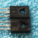
I have posted something about MJE340/350...and i did that twice
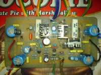
But i see people do not like to read...maybe because my threads are so big.
Here you have the transistors when i was testing and comparing them.
Alike you, i love to test things..but i use to take care, to have another amplifier to compare...as we think bass or treble increased and sometimes have not increased..we can be sure comparing only..having one amplifier standard and other with the modification
I did that using MJE340... after 2 pairs burned i realised sound was the same, but MJE340/350 was less stable.
We "think" things... and usually we are fooling ourselves..we spect modifications in sonics to every part we change..but this usually does not happens in real life... we have enormous imagination and we should be carefull with that...also our childrens are not the most clever ones, also our wife is not the most pretty woman or earth, and also we are not the best wide world amplifier designers.
You need to compare, a fair A to B comparison, controlled test, blind test... otherwise we are just fooling ourselves.
In my tests, MJE350/340 have not increased bass...have reduced the amplifier life.... as i had two pair burned!
regards,
Carlos
Attachments
The guarantee of reliability, stable operation and to be rid of troubles
goes to the amplifier with the transistors suggested, as the amplifier was tested and aproved using these ones suggested and printed into the schematic.
Also board should be Taj boards, the ones was tested too.
Guarantee will be void if modifications were done.
The amplifier is very sensitive to modifications and small mistakes, alike heatsinks ground missed.
I cannot take responsability about modifications, if people want to make them, be aware that may result fine or bad and that i am not responsable.
If result good, all i can do is to say congratulations to you..and if failed, that i am sorry.
Maybe dear Tinitus...maybe, but i would not try different transistors.
This amplifier has a lot of gain, so, it is sensitive..some carefull is needed, also very skilled folks building.
I have tried a lot of modifications, exactly to know what happens, and i could see that some modifications produces small oscilations superimposed to the waveform..something alike 5 percent of total amplitude of the signal, something you may not even listen...but depending the modifications this can be increased till total unstability and hard oscilations.
In special, Vas and Drivers are sensitive....the input cannot use 2N5401, and CCS cannot be modified too.
Several boards were made, to be sure it work stable, but i found that we can unstabilize the unit very easy too..so... i will keep people aware not to modify this one...this one does not forgive mistakes or non skilled people trying apply other parts, other values and modifications.
You could see..ekkart with other boards have perceive strange things in the bias..... Funky2x had troubles because wiring/construction.... a friend installed a 47pf in the place of 470pf and found problems till he found the mistake... this seems, the amplifier does not forgive errors.
regards,
Carlos
Last edited:
I did that using MJE340... after 2 pairs burned i realised sound was the same, but MJE340/350 was less stable.
Carlos
These devices are low current.
50ma is the maximum they can supply, so they can only be used
as VAS, but their performance are lacking compared with the BD139/140
pair.
Be aware that they are only 30mhz, while the BD139/140 have a Ft
that is in the 150mhz range.
The only thing they have is their high VCE, but that s all.
Otherwise, they are not good devices, even used as VAS.
I dislike them with no moderation......
Yes...that was found testing...i have only one pair..and will never use them
They will he here to remember me how much frustrations it produces.
I watch them with a lot of scare....others loves the unit....maybe they know something i don't about these transistors...maybe how to neutralise these fellows..... using a very big Cdom i can stop the ones..but this way i will have effects in my sinusoidal waveform above 25 Kilohertz.... it turns a triangle too much soon, when i use to have 60, 80 and 100 kilohertz in some amplifiers...say.... i can enter sinus and the waveform will be transformed in a triangle up these frequencies.
regards,
Carlos
Last edited:
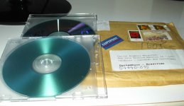
Thank you Rudi from Germany by the nice gift...those excelent Cds with special
music from North Europe...language seems not to be German.... excelent quality of audio, nice recording, beautifull woman voice.
Thanks a lot...delayed but customs have not blocked this one.
Gooooood!
regards,
Carlos
music from North Europe...language seems not to be German.... excelent quality of audio, nice recording, beautifull woman voice.
Thanks a lot...delayed but customs have not blocked this one.
Gooooood!
regards,
Carlos
Attachments
You see here the troubles a beguiner faces
I have translated what a very young brazilian builder answered me when i have asked him if Bias is adjustable...he was in panic, built two boards version and made the last boards i am using, he sent me by mail.
Here is the english version of his text.... see how troubled is, to a beginner, to adjust an amplifier, you see how a small detail can be confused:
" Carlos , here is your answer to the question you have made
asking me if i can increase and decrease bias
this problem appeared, measuring 28V in the 100 ohms resistance
happened in the first board that I did
I thought it was a defect.
When I did this my new board layout 1.4 and
and the same &$%& happened to this new
version board, i was reading 28V in the fuse
socket, fuse removed...the 100 ohms resistance, the
protector one was there.
And read what happened:.
The resistance of 100R of 2w i was using overheated
stinking to hell, and has burned in 10 seconds
so, i have sent you the big ones, the big 100R ones, to help,
because i knew they can warm to hell.
So, when i finish to build the version 1.4 board, the first bias
moment was measuring, also, the same old 28V and began
burned stink, then i hung up the amplifier and turned the trim to
the contrary direction, and this reduced to 2V only at the very
end of the trim range...when we listen to the click..
After that i trim it to 4 volts, i just realized that my board has bias
really adjustable, that can go back and forth, in good way, just
yesterday.... prior adjustments were difficult, the bastard small
trim screw do the adjustment slowly, i just had not time enougth
to adjust prior to see the protec resistance burning.
Yes, works back and forth, and stable, but when i touch the
VBE limiter transistor with soldering iron, the bias decreases,
I was happy, this transistor really works. "
regards,
Carlos
A tribute to Krachkiste, a real man, a helping hand, a decent man!
Mr. Krachkiste, from time to time, great guys appear in
our forum...people having natural ligth..you are one of
them.....you behave different, you explain what you mean,
you are a natural teacher, you wanna help and proved
that, as you made suggestion using direct mail, not
opening the subject to whole forum, so, not showing
yourself as beeing the “master of the universe”, or
the fried potatoes king.... you made suggestion because
worried, felt pity that felt i am in troubles, and made
that “out from the spot ligth”, not to appear wonderfull
or golden coloured, nor great or divine, not super, not
marvellous, but a natural gem, a precious man you are,
doing for free, to help forum, to help me to help forum...
only to help.
You see, others does not do this way..they give a huck
on me and on us, almost saying everything is wrong, that
i do not know what i am doing:
.They usually say something that sounds to me alike the bellow text:
- “the degrees of phase, in third and fourth and fifth ... more
3 quarters, are less than subliminary exponential electrolisis
of acid Electronics that remove bubbles in concrete massive
building shops... this will make up harmonics that will look
sissies when passing the output filter”
They enter with all that electronic babble, and leave happy
because could give one on me.... but really gave one in the whole
forum, as the kind of work i use to do, the dedication of my
time, is to the forum, and for the forum members and management.
So, they usually do not help, they prefere to give a huck on diyers
they love to stay bellow the spot ligth, on the scene, on the stage,
alike a show man, then they go away and let me look alike an idiot
there,... in the reality they make all of us idiots.
You helped..have explainded, so i will try next week as i have to
increase my room amplifier power, the one i use daily, to operate
using 65 volts supplies....then i will try your ideas, also remove that
thing...will give a try in your ideas, as i have to offer another amplifier
in March,28 ( a promisse)...so... resulting fine, you will be mentioned
as my inspiration.... the one have teached me, the one gave the
Tips and tricks, that has helped, in a humble way without
Be shinning in the forum.... so...helped me and whole forum
in advance and prior to help yourself, helped forum folks, amplifier builders,
and this without having personnal interests...only to help... a Christian alike
behavior, very much appreciated by me.
Thank you very much...I have understood 85 percent of your, ligthweigth,
carefull and kind technicall explanation... they were translated in simple words
to allow me to understand... a clear help, form a decent man, someone is one
more real forum friend.
Best regards,
Carlos
Last edited:
Drivers heatsinks must be distant from the board, not very good as they can be more stable touching the ground surface, not stand up supported by transistor leads...and to assemble them this way, then you will touch a 2K7 resistance, the bootstrapp one,
regards,
Carlos
Hmm... with a 13 x 19mm (.5" x .75") heatsink footprint (see BOM) should fit good. No guarantees if you use different parts. Warranty is void.
..Todd
- Status
- This old topic is closed. If you want to reopen this topic, contact a moderator using the "Report Post" button.
- Home
- Amplifiers
- Solid State
- Dx Blame ES .... based into the Blameless, i am trying a new amplifier