I was just looking at the direct drive amp for the Beveridge HB2 and noticed something peculiar.
Normally, in an ESL the diaphragm is biased to a high DC voltage, and the two stators are driven in opposite phase.
Looking at the Beveridge circuit, it seems different here.
It appears that the diaphragm is DC grounded and AC driven from one phase, while both stators are at opposite DC voltages (+/-3200V) but AC driven with the same signal, in opposite phase to the diaphragm.
What do you think?
Jan
Attachments
Mr Forsell, the swede with the Air turntable etc, made his own or modded his SW2 amplifiers. They sounded absolutley fantatsic - trule belivable rendering of a soundscape. Jazz at the Pawnshop was jaw-dropping. Maybe you should try to contact him but he seems to have left the stage...
//
//
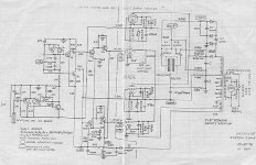
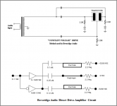
It does look odd , but this drive method enables you to get twice the voltage differential between the diaphragm and stators for a given amplifier output capability, so 2x the SPL. Essentially this is a form of amplifier bridging for ESLs. The downside is that it only works with highly conductive diaphragms. The transformer and direct-drive version of the Beveridge circuit topology are shown in attached pic....It appears that the diaphragm is DC grounded and AC driven from one phase, while both stators are at opposite DC voltages (+/-3200V) but AC driven with the same signal, in opposite phase to the diaphragm.
What do you think?
It is very similar in concept to the Final “inverted” circuit arrangement.
More details and comparisons between the two methods posted here:
Beveridge-vs-Final ESL Configuration
Attachments
So constant voltage as opposed to constant charge?
I always wondered this too - wouldn't constant charge "favor" one stator over the other? The Bev method (diaphragm grounded) alway made more sense to me. I just never knew it was conductive coating...
EDIT- disregard comment constant charge "favor" one stator over the other...brain fart...a lot more electronics needed for the Bev method...
Last edited:
Apologies for being a bit loose with my description.
The differential drive voltage is increased by 2x which results in 6dB increase in SPL.
Although a highly conductive diaphragm sounds like a simple solution, the low impedance conduction path results in corona generation which eats away at the coating unless voltage limiters are used in the design. The short life of many Final ESLs and later generation Beveridge PCB panels is exhibit A.
I own a pair. The diaphragm is fully conductive (zero Ohms). It's more or less "space blanket" material, remember those?
The diaphragm and stators are driven 180° out of phase so you get 3dB more from the same B+ voltage. This helps (I think) get more dBs from a 'stat before the air itself breaks down from EHT.
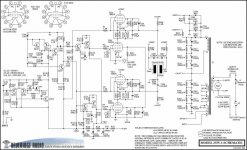
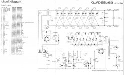
Here is a known accurate schematic.
The diaphragm and stators are driven 180° out of phase so you get 3dB more from the same B+ voltage. This helps (I think) get more dBs from a 'stat before the air itself breaks down from EHT.
Here is a known accurate schematic.
Attachments
The "Space Blanket" stuff is aluminized mylar. I bought a long roll of 6 micron from a Massage Parlor Vendor for like $25. Still have a mile of it. It is around 24" wide.
Re-Mylared a few ML CLS panels with this stuff. Worked a treat....but eventually ripped it all out and installed regular 6 micron mylar and sprayed it with Lichron Crystal...don't remember if it sounded any different...
Re-Mylared a few ML CLS panels with this stuff. Worked a treat....but eventually ripped it all out and installed regular 6 micron mylar and sprayed it with Lichron Crystal...don't remember if it sounded any different...
Carl, that schematic is easier to read. It also corrects some errors in the handdrawn one I had. The heater connection for the two top tubes is still not really correct, but 'those in the trade', as they would say at the Patent Office, know how it is connected to the power transformer.
On the the heater supply for those top tubes: those heaters swing with the output signal. Any capacitance on the top tubes heater (and cathode) to ground shunts away output current. I wonder if that transformer has special low capacitance windings?
Jan
On the the heater supply for those top tubes: those heaters swing with the output signal. Any capacitance on the top tubes heater (and cathode) to ground shunts away output current. I wonder if that transformer has special low capacitance windings?
Jan
Good question Jan, I have no idea. The specifics of this transformer are lost to history, I've never found them anywhere.
I wonder how tranny stray capacitance ratios against the known heavy capacitance of the panels? Maybe panel C is sucking so much juice that it swamps the transformer stray C? Just a guess...
And bolserst is right, the 'bridging' drive gets you 6dB, not 3 as I wrote. As an owner, I can say even with this headroom trick they don't play super loud.
On driving a capacitive load, aka an ESL. I've been doing some experiments (LTspice) on a push-pull direct drive idea, and noticed something I hadn't realized before.
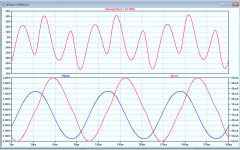
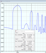
See attached, showing in the bottom panel Vout of the amp and Iout, the current through the 500pF load cap. The top panel shows the distortion waveform of Vout, mainly some 1.8% 3rd.
I you look at Iout you see clear zero current crossing distortion, while Vout doesn't. That had me wondering, how can the voltage across and the current through a linear (spice-ideal) capacitor be different in shape?
But if you think of it as two signals, the 1kHz fundamental and the 3kHz 3rd, you realize that the impedance of the load cap for these two signals is different!
For the 3rd, the load cap presents 1/3rd the impedance than for the 1kHz fundamental, so the 3rd load current will be three times as large than for the fundamental, per volt of signal.
The effect is that the distortion in the load voltage will be magnified in the load current. The magnification is by a factor f/f(fund); for the 3rd, the increase would be a factor 3.
Jan
Attachments
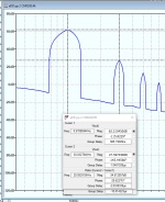
If you look at it in the frequency domain, it is just as expected. The attached shows the spectrum of Vout, showing about -34.5dB distortion, about 1.8%.
Looking at the load current though you see that the 3rd is about -25dB, about 5.6%.
The ratio of 5.6/1.8 (or -34.5 - -25dB) is almost exactly the factor three as predicted in my previous post.
Now, this all seems obvious in hindsight, but I never realized this. Was this common knowledge to you guys?
I think this also places an additional requirement on the driving amplifier.
Jan
Attachments
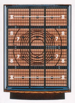
One other issue. In the usual schematics for the ESL63 that float around, see attached sch_2, it appears that the two bass panels are not driven in parallel.
Rather one is driven following the other through some series resistors.
Is that correct? Are the bass panels not driven in parallel?
The conceptual schematic (overall block diagram, also attached) seems to show they are, and to me that would make more sense. So what's up - in the detailed schematic, should LH side of R6 and R8 not be connected to the junction of R3/R5 and R4/R7?
Jan
Attachments
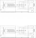
Attached is a later version of the ESL63 schematic that makes the panel segmentation connectivity clearer....In the usual schematics for the ESL63 that float around, see attached sch_2, it appears that the two bass panels are not driven in parallel.
Rather one is driven following the other through some series resistors. Is that correct? Are the bass panels not driven in parallel?
The conceptual schematic (overall block diagram, also attached) seems to show they are, and to me that would make more sense.
So what's up - in the detailed schematic, should LH side of R6 and R8 not be connected to the junction of R3/R5 and R4/R7?
I think it should address your question.
***
BTW, the block diagram in the first picture of your post is for the ESL57 not the ESL63.
Attachments
Last edited:
Interesting! thanks for sharing....The effect is that the distortion in the load voltage will be magnified in the load current. The magnification is by a factor f/f(fund); for the 3rd, the increase would be a factor 3.
Do you have a working DD amp prototype that you could measure to see if this amplification of H3 shows up in the acoustic response of the driven ESL?
I am curious if in your LTspice modeling adventures you have evaluated adding a substansitial resistive load(like the old Sander's amp) to swamp the effect of the capacitive load?
If so, what effect did it have on your distortion profile?
Yes I have seen that schematic but it clearly is not electrically correct, it's a peculiar mix of electrical and hierarchical views, so I don't know what conclusions to draw from it.Attached is a later version of the ESL63 schematic that makes the panel segmentation connectivity clearer.
I think it should address your question.
***
BTW, the block diagram in the first picture of your post is for the ESL57 not the ESL63.
What interests me primarily is whether the bass panels are indeed driven in parallel or not.
Jan
I'm not yet able to easily do such a test, but will for sure when I have a working setup.Interesting! thanks for sharing.
Do you have a working DD amp prototype that you could measure to see if this amplification of H3 shows up in the acoustic response of the driven ESL?
I am curious if in your LTspice modeling adventures you have evaluated adding a substansitial resistive load(like the old Sander's amp) to swamp the effect of the capacitive load?
If so, what effect did it have on your distortion profile?
I know that the load an ESL presents is not purely a capacity, otherwise no work would be performed and no sound heard, so the phase shift will be less than 90 deg. There will be some resistive component.
The ESL63/989 with their transmission line setup surely will not present a capacitive-only load, so for those speakers the point could be moot.
Pure capacitance/unsegmented units may show the effect though.
Jan
Yes, the upper and lower panels(aka bass panels) are driven in parallel along with the outer portions of the middle 2 panels.Yes I have seen that schematic but it clearly is not electrically correct, it's a peculiar mix of electrical and hierarchical views, so I don't know what conclusions to draw from it.
What interests me primarily is whether the bass panels are indeed driven in parallel or not.
Jan
All areas labeled with an "8" in the 2nd panel picture are driven from the output of R6 and R8.
The ESL63 does present a substantially resistive load(ie phase < 30deg) between 200hz and 10Khz, if that is the target load for your DD amp....I know that the load an ESL presents is not purely a capacity, otherwise no work would be performed and no sound heard, so the phase shift will be less than 90 deg. There will be some resistive component.
The ESL63/989 with their transmission line setup surely will not present a capacitive-only load, so for those speakers the point could be moot.
- Home
- Loudspeakers
- Planars & Exotics
- Driving the Beveridge ESL