assembly
Any help to is much appreciated
thanks
kp93300
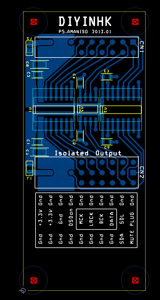
I have the isolator in hand and would like to know the orientation of the texas isolator before soldering.
I only using it as isolator between the amanero combo converter and the BII dac
Please see the attached
1)Is the isolator orientation correct ?
2) The arrows point to the isolated BC ( bit clock )output?
3) The corresponding pin on the left side of the image corresspond to the BC input ?
4) Where to apply the dc voltage in ?
thanks
kp93300
Any help to is much appreciated
thanks
kp93300
Attachments
Last edited:
Any help to is much appreciated
thanks
kp93300
I guess nobody is going to support the free board...
the bar on the board pattern for the parts (indicated on the pic on first post of this thread) indicates the side that will be pin 1 and 16, as is the standard. pin 1 is indicated by the dot on the isolator
Last edited:
Why did this thread seize with qusp departure? Has anyone actually finished the board build up? I just got my boards (9018 and USB) and I am starting the build. KlipschKid thanks for the BoM. Any news on the build progress KlipschKid and glt? Guys your contributions are greatly appreciated by a ES9018 newbie like me. I built a TP OPUS so far thats it so this is a new exciting adventure for me.
KK has been updating his build in his blog: ES9018 | myl8test
I've been dragging my feet ordering parts...
I've been dragging my feet ordering parts...
I am still puzzled and confused with some of the postings: glt you are talking about a need for 1.2V supply, in addition to 3.3V AVCC and 3.3V DVCC. However I don't see a need for a 1.2V regulator for a v2 board. I just got my v2 board and it has AVCC, DVCC and additional 3 pins marked +12, GND and -12V. I don't get it why does this board require +-12V PS? I am yet to figure out where to source AVCC power supply. For +-12V (if really needed) I will use a TP Placid bipolar PS and for DVCC 3.3V I will use ADP7104 eval board. Any recommendations for AVCC 3.3V regulator?
there are limitless possibility, I hope everybody can share their experience and modification to the others
there are still many free pcb to go! All are welcome
Please remember to left the needed qty(1or2) in the paypal payment notes, of 1 will be shipped in default. happy diying to all")
there are still many free pcb to go! All are welcome
Please remember to left the needed qty(1or2) in the paypal payment notes, of 1 will be shipped in default. happy diying to all
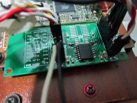
This is my build of the board with iso7240 from texas.
I test it just now.
The input of the isolator has 3.3V supply from the amanero board . It measure about 3.2 on the isolator board. The output of the isolator has a 4.8V power from another source. The amanero usb i2s board is powered from the usb input itself.
There is sound but music is very soft with very prominent background hiss that correspond to the volume pot.
what are the likely problems ?
I appreciate input from more able diyers .
thanks
kp93300
Attachments
I want 1 isolator bare PCB, how much have I to pay and what's the paypal account to pay. Also I need link to B.O.M.
TIA
Felipe
Two boards please.
Hi Felipe
BOM is described in first post.
Paypal account is : ppdiyinhk@diyinhk.com
I've placed an order this morning.
Phil
BOM is described in first post.
Paypal account is : ppdiyinhk@diyinhk.com
I've placed an order this morning.
Phil
- Home
- Vendor's Bazaar
- diyinhk Store