Could anyone reference me to a decent circuit using and ESS chip and preferably op-amps for the output stage, I want to have a play doing an HDI PCB layout to see how small I can get the circuitry.
Cheers
Marc
Well this chip for a start has no need for opamps on the output - perhaps this might be better in a seperate thread ?
...
An externally hosted image should be here but it was not working when we last tested it.
Dude, that's I2S and should be as short as possible!
These ES9023 boards are great; I'm groovin' on an old CS4329 eval pcb, a 1545 pcb (switched to I2S format), and a WM8805 pcb.
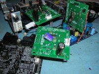
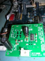
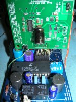
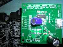
Super fun and ... they sound half decent too!
Last edited:
I know... the connection in the picture is 8cm long. For evaluation that was ok.Dude, that's I2S and should be as short as possible!
The final configuration will have a footprint as small as possible and I guess the connection will be less than 3cm. I hope there is enough space for four Calvin Buffers too. Maybe that can lift the sound from half decent to fully decent
i have the DIYINHK es9023 DAC and have installed a crystek cchd-957 oscillator.
however, i cant get it to show up on the PI as an I2S sound card. do i need to supply separate 3.3 voltage to the oscillator to get this to work or is that just an optional feature?
are these the only steps needed?
1) supplying the DAC with voltage
2) add the 50mhz oscillator to the pre-allocated spot on the board
3) connect it to the PI P5 header
4) configuring the PI for i2s
thanks,
greg
i have the DIYINHK es9023 DAC and have installed a crystek cchd-957 oscillator.
however, i cant get it to show up on the PI as an I2S sound card. do i need to supply separate 3.3 voltage to the oscillator to get this to work or is that just an optional feature?
are these the only steps needed?
1) supplying the DAC with voltage
2) add the 50mhz oscillator to the pre-allocated spot on the board
3) connect it to the PI P5 header
4) configuring the PI for i2s
thanks,
greg
Just thinking out loud here - should you also need to cut the MCLK trace for Async?
i have the DIYINHK es9023 DAC and have installed a crystek cchd-957 oscillator.
however, i cant get it to show up on the PI as an I2S sound card.
The RPi will never actually "see" the DAC. I2S is not capable of doing that.
If the RPi is configured properly, it will just assume that you have a DAC connected and begin outputting sound through the I2S lines.
do i need to supply separate 3.3 voltage to the oscillator to get this to work or is that just an optional feature?
It appears to be optional. I am of course assuming that you have installed the other necessary components (an SMD capacitor and an SMD ferrite bead (or just a jumper)). Plus, I am not sure whether the en_osc jumper is necessary too.
No and I do high speed digital layout everyday. Do you know what actually makes a design high speed, no I didn't think so, but it is not the clock frequency that a device is running at.
As I said any digital above 1mHz benefits from a full contiguous ground plane.
Now the chances are I do know an awful lot more about laying out digital circuits than you do, and no I am not living in the dinosaur age, so unless you know what you are talking about don't patronise me.
Hi, a quick question for you that has experience with digital signals:
What would be the best style of the ground plane, the solid or the one with dozens / hundreds of "holes", and why. thanks for listening.
A solid ground plane is best....though you do end up with holes for vias.
The main reason is so the signal has as near a contiguous return path as possible.
I do presume when you said with holes in you meant a cross hatch ground plane, I have never done one on a standard PCB and have only seen a few done ever...
Basically having holes in your ground and the signal running over a hole is bad news...
Slots in Ground Planes
ok, thanks for replying, you guessed correctly, less last paragraph of your message, this was not what I meant, anyway I will illustrate, this is a simple dac:
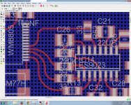
Now, I presume, the lower the capacitance is desirable traits, right? Let's analyze the most visible trace in the image, which is (MLK) if you look carefully you will realize that it continuously keeps on ground, but not totally, consequentemente the capacitance is reduced because there is less parallelism in such gnd,
what you think?
You never see ground planes done like that, they are all solid copper pours. The capacitance isn't that much and is not a concern, having a solid plane for return signals is much more preferable. As I said on ridged PCBs I have never done a ground plane that was hatched and I have probably only seen a couple in the last 30 years, it serves no purpose and splits the ground up for the return current.
I wouldn't bother with curved traces either, 45 degree corners are just as good and easier to lay out.
The text file has a few links relevant to PCB design if you want to learn more.....
I wouldn't bother with curved traces either, 45 degree corners are just as good and easier to lay out.
The text file has a few links relevant to PCB design if you want to learn more.....
Attachments
This is an excellent calculator for all sorts of PCB related requirements, including a trace impedance calculator...worth downloading and playing with:
Saturn PCB Design - PCB Via Current | PCB Trace Width | Differential Pair Calculator | PCB Impedance
Saturn PCB Design - PCB Via Current | PCB Trace Width | Differential Pair Calculator | PCB Impedance
- Status
- Not open for further replies.
- Home
- Source & Line
- Digital Line Level
- Diyinhk ES9023 $20 on Ebay
