Yes, increasing big ccs current slightly reduces offset but only slightly, from .3 to .25v
we have progress, you are on track now, can you post a pdf version of you schematics, these tired old eyes are hard up looking at your simulation pictures...
i remember i also asked you the polarity of the 0.3 mV,? is it positive or negative?
Running out of ideas
Me too.
As you replaced both the input and the power devices by some others with basically different principles of operation, I'd say you have got quite another amp that, perhaps and at it's best, just might resemble the Honey Badger, but isn't it anymore. I'm sure, though surely being no guru in that, it may need another compensation strategy, if not a complete another schematics that fits to your devices better.
As this discussion here strongly tends to get somewhat confused, not to say shattered, I'd like to ask the moderators to move these off-topics to another thread, in favor of keep staying on topic. We've yet got too much threads in this board where the running discussions no more have anything to do with the thread topics, e.g. the thread on Apex' 100W Ultimate Fidelity Amplifier - and many more. Thank you.
Best regards!
You are perfectly right, I will move my comments here http://www.diyaudio.com/forums/soli...r-amplifier-assemblage-vii-5.html#post4934296 hoping Andrew T and AJT and everyone that wants to help will follow.
Reduced feedback and oscilation remains now at 250khz
Running out of ideas
you have two issues, first is the offset, and then oscillation...
i think you have to kill the oscillations first, the offset is easy...
you have two issues, first is the offset, and then oscillation...
i think you have to kill the oscillations first, the offset is easy...
in order to not create confusion I moved this discussion here: http://www.diyaudio.com/forums/soli...r-amplifier-assemblage-vii-6.html#post4980619
Allready tamed the oscilation
I would really apreciate your input in the other thread AJT
Has anyone looked at alternate VAS topologies for the Badger?
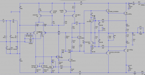
I added a buffer between the VAS and EF2 OPS of a very badger-like amp. Douglas Self shows such a buffer as figure F in his diagram of possible VAS variants:
This keeps the VAS transistor sinking a near-constant 3mA. From the VAS' point of view, the buffer makes the EF2 look a lot like an EF3, a much lighter load. Could we call this an EF2.5 output?
Before and after schematics are attached. Q14 and R11 are the additions. I also adjusted the CCS feeding the VAS from 4.5mA to 9mA. (The VAS with output buffer can sink more current, shouldn't we be able to source more too on the other side?) The new version simulates with a lower distortion floor, about 10db lower. It's not a bad return for adding two elements.
Note the SOA protection circuitry dumps current to the VAS transistor, not to the buffer.
It's playing now. Subjectively this mod seems to help the amp play into a 4 ohm load (Klipsch Fortes) that it was sounding dull with before.
Attachments
Hi Terry,
that is not the final V2.4 as doesnt have baker clamp diode.
I do not the background why lay file of badger is required here, but i have created a badger v2.4 clone layout, that matches the schema and OS's layout (more or less, silk font is vector graphics). can it help?
reg
Prasi..
i will read previous posts to understand...I apologize if i am walking forbidden territory...
Last edited:
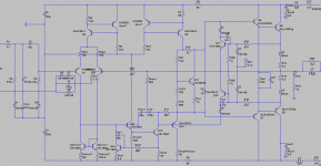
Oops! The "EF2.5" OPS above oscillates, which can be fixed with emitter degeneration on the buffer. New schematic attached.
It was oscillating with no load, with amplitude ~100mV and at a few 10s of MHz. It wasn't enough to be destructive, but let's not gamble. The oscillation happens on the real amp, and you can see it in simulation by removing the load and putting 600nH of parasitic inductance in series with the Zobel network. The real amp has a nice long Zobel return wire back to the ground star, it must be 100s of nH at least.
What loop was oscillating? It's not the global NFB loop or TMC loop; if you break both of those with 1GH inductors, AC sim still shows peaking. My guess is that this is the well-known effect where an EF, or chain of EFs, can oscillate in the absence of enough load. Adding the EF2.5 buffer makes this amp more prone to it. You want EF3-like performance, the cost is EF3-like stability concerns.
Base stoppers at the drivers and outputs help some too. A base stopper at the predriver buffer makes stability worse in simulation, oddly.
The revised design is below. I also replaced the KSC1845s in the current mirror with transistors that are free of quasi-saturation behavior.
So there you have it, the EF2.5. It's near-EF3 performance, can be retrofitted onto an EF2 OPS by adding one Q and two R's. It's probably stable? Have fun")
It was oscillating with no load, with amplitude ~100mV and at a few 10s of MHz. It wasn't enough to be destructive, but let's not gamble. The oscillation happens on the real amp, and you can see it in simulation by removing the load and putting 600nH of parasitic inductance in series with the Zobel network. The real amp has a nice long Zobel return wire back to the ground star, it must be 100s of nH at least.
What loop was oscillating? It's not the global NFB loop or TMC loop; if you break both of those with 1GH inductors, AC sim still shows peaking. My guess is that this is the well-known effect where an EF, or chain of EFs, can oscillate in the absence of enough load. Adding the EF2.5 buffer makes this amp more prone to it. You want EF3-like performance, the cost is EF3-like stability concerns.
Base stoppers at the drivers and outputs help some too. A base stopper at the predriver buffer makes stability worse in simulation, oddly.
The revised design is below. I also replaced the KSC1845s in the current mirror with transistors that are free of quasi-saturation behavior.
So there you have it, the EF2.5. It's near-EF3 performance, can be retrofitted onto an EF2 OPS by adding one Q and two R's. It's probably stable? Have fun
Attachments
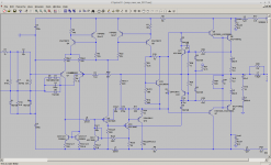
You're right. That puts a shelf back into the response roll-off at about 20MHz. Thanks. This design needs a clean RC zobel.In the simulation your zobel inductance is shunted by R29 and the load resistor. Give the load about 1uH of inductance or more like we would see in real life.
But the Forum shop has not responed to my Email request for update information.Jason reports that we'll have boards in the store in about a month
Did any Member get update information?
I think this confirms what I have been saying for a long time.You're right. That puts a shelf back into the response roll-off at about 20MHz. Thanks. This design needs a clean RC zobel.
The inductance in the route from output devices through the output Zobel and back to the decoupling attached to the output devices needs to be kept low.
This means short leads, short traces, compact low loop area for the whole route from device and back to the device.
Remember the current MUST return to source. In this case for the output Zobel, the source of Zobel current is the output device.

This is the alternative Zobel arrangement proposed by Thiele.Yes, and the Zobel network must not be connected after the output coil, across the speaker posts just for convenience, as it is to be seen sometimes.
Best regards!
Leach adopted it.
Cherry discusses it.
I don't know how much the extra inductance in the route will affect the Zobel performance.
- Home
- Amplifiers
- Solid State
- diyAB Amp - The "Honey Badger"