I totally agree that the holes are too small. I think I've reported this already a while ago (have to admit I can't remember where, maybe via the online store feedback thingy?). I ended up drilling all resistor holes because it was a PITA hit-and-miss when fitting the resistors (I mostly used Dale CMF).
I did not know we could drill the holes without fear of cutting the connection between the pads and the tracks.
I did not know we could drill the holes without fear of cutting the connection between the pads and the tracks.
Drilling will destroy the via connections between top and bottom layers. That's not a problem as long as this connection is not necessary to make the connections of the circuit. As far as I can tell, that is not the case for the resistor holes in the diyAudio boards. If it is, it's easy to fix by soldering the wire on both sides of the board.
Most of the pads are on the trace side ONLY.I did not know we could drill the holes without fear of cutting the connection between the pads and the tracks.
There are very few pads relying on the plated through hole. That was one of my complaints.
A plated through hole that has no connecting pad on one side can safely be drilled out to a larger size.
There is ONE resistor pad on the top side (R6) that relies on the through hole for a connection. If you need to drill this ONE hole out, then scrape off the paint/epoxy on the top side and solder the resistor lead to the newly created pad.
Last edited:
Hi guys, just finished mounting in the chassis a portion of the HB build, the layout I have chosen is in the pictures attached, would that be ok?, did anyone had issues with 50hz humm ? both boards were tested and they seem to work fine, all the adjustements said in the guide were done, on the TP1 and TP2 I have set it to get about 25mV, nothing is overheating so far in a full load test for a couple of hours , it sounds much much better than my "fancy" Denon receiver, it has more umff and even at lower levels it sounds punchier. All the tests were done on 20000uF per side power supply and its very quiet, no humm , just a extremely low hiss when it gets connected to my PC. The two vertical boards are in that position hoping to shield a lttle the amp board from the transformer (I hope it will also behave that way once powered up in the case). The small board on top of the toroidal is DC filter that is actually working , I have very little noise from the transformer when is in the circuit, when I take it out it's quite audible and it varies in intensity .
Line level for a onboard sound card is about how much?
Please any suggestions or what would be best to do in this chassis that now seems a bit small with everything inside.
Pictures here :
Imgur: The most awesome images on the Internet
Thanks.
Line level for a onboard sound card is about how much?
Please any suggestions or what would be best to do in this chassis that now seems a bit small with everything inside.
Pictures here :
Imgur: The most awesome images on the Internet
Thanks.
Last edited:
Planning out Honey Badger (2 boards, i.e. stereo)
What are the advantages of using one transformer and 2 PSU boards vs one transformer and one PSU shared by two Honey Badger boards?
So far the plan is to use AN-8445 - 800VA 45V, I assume it will be sufficient power for the entire setup.
2 transformers 2 PSU is not an option due to size/cost limitations
Planning out Honey Badger (2 boards, i.e. stereo)
What are the advantages of using one transformer and 2 PSU boards vs one transformer and one PSU shared by two Honey Badger boards?
So far the plan is to use AN-8445 - 800VA 45V, I assume it will be sufficient power for the entire setup.
2 transformers 2 PSU is not an option due to size/cost limitations
+1 for Kay Pirinha's answer. As far as I can tell, the AN-8445 does have two separate 45 V secondaries, so you could go full "dual mono" up to the primary winding of the transformer, improving the crosstalk between the two channels. This is also described in the diyAB Honey Badger build guide, I believe.
Last edited:
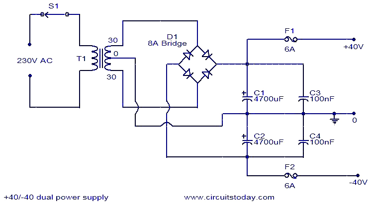
I see. I was under impression that each PSU board (the entire Universal PSU with 8 caps and 8 diode arrays) takes input from two transformer secondaries (45V of AC each) and outputs +/- 60 of DC required by one Honey Badger board. Sort of like on this diagram here (below). Am I wrong in this?
I see. I was under impression that each PSU board (the entire Universal PSU with 8 caps and 8 diode arrays) takes input from two transformer secondaries (45V of AC each) and outputs +/- 60 of DC required by one Honey Badger board. Sort of like on this diagram here (below). Am I wrong in this?
Oooops, my bad! Of course you need 2 x 45 VAC secondary windings for a single +/- 60 VDC supply. For a dual-mono PSU, you'd need four 45 VAC secondaries. So then Antek transformer you mentioned is not suitable for a dual-mono PSU. Sorry for the confusion.
If you can't find a suitable off-the-shelf transformer, you could just order a custom transformer according to your specs. Custom transformers are usually not (much) more expensive than off-the-shelf types.
A pair of secondary windings can feed into one PSU.As long as both PSU boards share one secondary winding with CT, I don't see any, besides of that you probably may install more total capacitance.
A real benefit would be if the transformer had separate secondaries for each channel.
Best regards!
It does not make any difference whether you use two isolated secondaries or a centre tapped secondary when powering a single channel.
You can use the single PSU to power a stereo amplifier. There is no advantage as far as I can tell to using two PSUs fed from one pair of secondaries.
Using two PSUs fed from one pair of secondaries causes sufficient complication of the Zero Volts wiring that most Builders get this very wrong and end up with avoidable hum & buzz. I suggest you don't try doing a stereo build from two PSUs on a single pair of secondaries.
If you have a four secondary transformer. You can build two isolated PSUs and feed a pair of isolated audio channels. This gives a dual mono build where only the transformer primary is shared between the channels. this saves money and space and weight compared to a dual mono based on two transformers. Performance of the quad seconadry is almost as good as a true dual transformer dual mono build.
Only a monoblock performs better than these.
Note the connection from the centre tap to the first Zero Volts between the smoothing capacitors.I see. I was under impression that each PSU board (the entire Universal PSU with 8 caps and 8 diode arrays) takes input from two transformer secondaries (45V of AC each) and outputs +/- 60 of DC required by one Honey Badger board. Sort of like on this diagram here (below). Am I wrong in this?
This LINK becomes common to all the channels fed from the PSU.
Even putting in two PSUs does not get around that LINK between the channels.
This LINK must be kept short and very low resistance/impedance. Any sharing of this LINK will result in LOOPS. That causes interference. Keep the LOOP small in area and low in impedance, otherwise the interference becomes measurable and audible.
Remove C3 and C4. They increase the risk of ringing if the transformer is presented with a fast changing step in current demand.
If you decide to add in some ringing attenuation, then it must be fitted at the transformer output leads, NOT at the PSU output.
This ringing attenuation is called a "Snubber" and is fitted between your labels 30 and 0 and from 0 to 30. The two "Snubbers" consist of a series combination of capacitor and resistor. NOT a ringing inducing capacitor alone
Last edited:
Andrew, thank you for the detailed answer. I ended up with one PSU for my setup. Ordered the Universal PSU from diyAudio store (no, I was never going to build the power supply from that schematic that I quoted, it was there just to clarify my answer to mbrennwa).
I bumped up the caps on the Universal PSU to 8x15K and going with 1000VA transformer. Hopefully this will be enough for the Honey Badger although this also means (does it?) slow start will be a necessary addition in the near future.
I am also getting a Cheapomodo to tune up those snubber components of the PSU. It is going to be a lot of fun! Last time I built an amplifier was in high school... it is like reliving those times.")
I bumped up the caps on the Universal PSU to 8x15K and going with 1000VA transformer. Hopefully this will be enough for the Honey Badger although this also means (does it?) slow start will be a necessary addition in the near future.
I am also getting a Cheapomodo to tune up those snubber components of the PSU. It is going to be a lot of fun! Last time I built an amplifier was in high school... it is like reliving those times.
they allow you to check quiescent current when first starting the amplifier with the output bias set to zero.
I don't recommend fuse bypasses that could extend the time that an excessive current can pass.
I used 100mW smd on the bottom side rather than big through hole on the top side.
I don't recommend fuse bypasses that could extend the time that an excessive current can pass.
I used 100mW smd on the bottom side rather than big through hole on the top side.
I had 1/4 Watt thru hole resistors and the first fuse blow gave soot in the air and black spots around PCB. I removed them and never put them back since. My understanding you don't need them in the finished board that you are done testing.
Now, here is the question that bothers me lately. I know this board has no speaker short circuit protection. Has anyone looked at the schematics to understand what will likely happen in case in the unfortunate case you short a speaker out? I am taking this amp on a trip, should I just bring extra fuses or does short circuit mean the party is over?
Also, do you think there is a relatively easy way to add the protection as an add on? Say, replace R49 with something that detects overload and shuts the power off?
As a bare minimum the amplifier should have a DC detection circuit on the speaker outputs and good quality relays able to disconnect the speaker outputs if an output device shorts. This will ruin a speaker instantly. Shorting the speaker output leads usually leads to instantaneous destruction of output devices. Output devices normally blow faster than fuses open. Fuses are in place to protect the power supply from a shorted output stage. It's wise to monitor output stage current and heatsink temperature too, and shut things down if they get out of control. If you want a state of the art complete protection package check out this thread. How to build a 21st century protection board These systems are very reliable and have saved many amps and speakers.
Virtual Zero Audio - power amplifier products
Virtual Zero Audio - power amplifier products
Last edited:
- Home
- Amplifiers
- Solid State
- diyAB Amp - The "Honey Badger"