how about building the amp as designed first and them have a listen,
and then post your intended mods...this way you have a baseline with which to compare...
otherwise you may be running all over the place that may lead nowhere...
we do not know your level of competence so this is what we advise,
otherwise if you are a designer like Ostripper, by all means engage him...
It has nothing to do with modifying anything. It's no use trying to improve on something I haven't even built yet. Besides that, I am quite new to all of this. I'm just trying to make sense of the component- and setup-options: why pick one in favour of the other. But it seems I'm making this more difficult than it is.how about building the amp as designed first and them have a listen,
and then post your intended mods...this way you have a baseline with which to compare...
otherwise you may be running all over the place that may lead nowhere...
we do not know your level of competence so this is what we advise,
otherwise if you are a designer like Ostripper, by all means engage him...
Thanks anyway!
So, this is what I've come up with.
No changes, just trying to make informed choices. Am I going to be ok with this?
2x PSU:
PCB: DIYaudio Universal PSU V3
Transformer: 625VA, 40-0-40V, sec. 7,80A nom (e.g.: Multicomp MTCA625/40)
Caps: 10kuF, 80V (e.g. CORNELL DUBILIER* 380LX103M080A052)
Snubber caps: to be determined, based on transformer.
Wire and grounding scheme: will get to that when actually building.
Amp:
Voltage rails: ca. 56,5V
Cascode: Q1,Q2: ksc1815 (reason: lower hfe -> less likely to cause oscillation, if I read and understood correctly. OS, thoughts?)
Cascode ref.: 15V Zener (thoughts: voltage does not depend on rail voltage or power rail voltage sag. Again: is this correct thinking?)
Q16-18/Q19-21: 2sc5200 / 2sa1943 or 2SC3263 / 2SA1294 (whis is “better” and why? Will both work without any changes to the amp as it is?)
C12, C16: do I understand correctly that these need to be X7R type?
Any and all constructive input is very much appreciated. Thanks!
James.
One more question: when buying transistors of a certain type, is it possible that you get different hfe's? If so: do you need to match this in all cases? And how can I do that? Can you do this with a DMM that can measure transistors? Like this one: http://www.aliexpress.com/store/pro...igital-multimeter-diode/209668_528166439.htmlhttp://www.aliexpress.com/store/pro...igital-multimeter-diode/209668_528166439.html
So, this is what I've come up with.
No changes, just trying to make informed choices. Am I going to be ok with this?
2x PSU:
PCB: DIYaudio Universal PSU V3
Transformer: 625VA, 40-0-40V, sec. 7,80A nom (e.g.: Multicomp MTCA625/40)
Caps: 10kuF, 80V (e.g. CORNELL DUBILIER* 380LX103M080A052)
Snubber caps: to be determined, based on transformer.
Wire and grounding scheme: will get to that when actually building.
Amp:
Voltage rails: ca. 56,5V
Cascode: Q1,Q2: ksc1815 (reason: lower hfe -> less likely to cause oscillation, if I read and understood correctly. OS, thoughts?)
Cascode ref.: 15V Zener (thoughts: voltage does not depend on rail voltage or power rail voltage sag. Again: is this correct thinking?)
Q16-18/Q19-21: 2sc5200 / 2sa1943 or 2SC3263 / 2SA1294 (whis is “better” and why? Will both work without any changes to the amp as it is?)
C12, C16: do I understand correctly that these need to be X7R type?
Any and all constructive input is very much appreciated. Thanks!
James.
12 or 15V zener will do.
Cascode itself ( Q3/4), takes most of the rail voltage - so , ksa992/c1845 here.
Q1/2 - npn LTP and Q5/6 - pnp CM are left with 15V and 3 V.
I'm successfully using current stock Ksa1015/c1815 - G grade on my wolverine (same circuit).
I measured Hfe of 175 - 180 on both "G" grades from mouser - very consistent.
My caution of using very high beta Q1/2 was because of a particular build. This
could be fixed with higher Re at LTP.
1943/5200 , NJW0281/0302 , and 2SC3263 / 2SA1294 all run the same
on the badger.
Tests on my OPS's only show less than a few mV change in bias with
the different outputs used. Of the 3 , the NJW's seem to have the best
consistency .... less than 1/2mV current sharing differences in a 5 pair OPS.
2SC3263 / 2SA1294 on another amp differ up to <2mV.
But , they all sound the same (awesome) ...
Edit - as discussed before ..... choose away for your decoupling caps.
X7R is alright (but others will not fail/explode).
OS
Last edited:
Beautiful boards, a pleasure to to solder.
I'm populating my boards now, I've finished designing the case. I enjoy building cases, each one is different and unique. They sort of build themselves.")
When adjusting R7 Trimmer to the recommended 85 Ohms, should I measure from Pin 1 to pin 2?
Thank you for the help.
Ron
I'm populating my boards now, I've finished designing the case. I enjoy building cases, each one is different and unique. They sort of build themselves.
When adjusting R7 Trimmer to the recommended 85 Ohms, should I measure from Pin 1 to pin 2?
Thank you for the help.
Ron
Thanks OS.
I was asking about trimmers in general. In the build manual it says to set R7 to 85 Ohms.
In general, prior to soldering the trimmer on the board should we measure between posts 1 and 2 then set the recommended Ohms?
I'll measure the voltage across R14 when I "fire it up"
Ron
I was asking about trimmers in general. In the build manual it says to set R7 to 85 Ohms.
In general, prior to soldering the trimmer on the board should we measure between posts 1 and 2 then set the recommended Ohms?
I'll measure the voltage across R14 when I "fire it up"
Ron
the "adjusted" resistance depends on which two pins are shorted. That is determined by which orientation fits the PCB.Thanks OS.
I was asking about trimmers in general. In the build manual it says to set R7 to 85 Ohms.
In general, prior to soldering the trimmer on the board should we measure between posts 1 and 2 then set the recommended Ohms?
I'll measure the voltage across R14 when I "fire it up"
Ron
The better way, if you can't work it out before soldering, is to measure the resistance as soon as you solder it in and SET the resistance to give minimum bias voltage. This is usually minimum bias voltage = maximum VR resistance.
R7 adjustment ....
The nice thing about the badger topology , any R7 adjustment (even 0R) will
just affect the LTP current.
10R is 3.2ma per device and 190R is 1.3ma. But , VAS current stays at 7ma ,
regardless.
The 90R suggested setting sets Q1/2 to @2ma (optimal for ksa/c's) , but the
amp would not be destroyed by even a shorted trimmer (it would actually still work).
PS - I does not matter , but R14 can be 1K. With 1K- voltage=mA. This is
a present upgrade to all my IPS's. (ease of adjustment)
OS
Thanks Andrew. I appreciate the explanation. Ok it makes sense now, I was thinking that all 3 pins had to be used. If only 2 are used it would be easy to adjust resistance to the desired level. My error was thinking voltage goes in pin 1 , shunted to ground on pin 2, then output on pin 3 I'm learning! Due is gun soldering.
Hi,
a question about the PSU. Do the buffer capacitors need to meet any specific requirements? Given the RF-snubber in the PSU, the HF-decoupling in the amp itself and the potentially large current draw, I'd think only low ESR is important. But I'm definitely no expert... Far from it. So any advice is appreciated. Anything else I need to pay attention to?
a question about the PSU. Do the buffer capacitors need to meet any specific requirements? Given the RF-snubber in the PSU, the HF-decoupling in the amp itself and the potentially large current draw, I'd think only low ESR is important. But I'm definitely no expert... Far from it. So any advice is appreciated. Anything else I need to pay attention to?
Hi,
After having build an Aleph J to power my Avantgarde Uno's with boards from the shop, it may be time for something different...
I just bought a pair of Apogee Calipers that need restoration. When (if?) I get them in working condition, I will need an amp to drive them. The Calipers have an impedance of some 3 Ohms: will the Honey Badger cope with this?
If so: It will surely mean that I should not use too high rail volts, can anyone give some pointers on the PSU voltage (35V AC transformer?) and the power rating of the transformer?
Regards,
35+35Vac will give supply rails around +-50 to +-51Vdc
expect the maximum output into 3r0 to be around 38 to 39Vpk.
38Vpk into 3r0 is equivalent to 240W into 3ohms.
That is a lot of power to expect from the output transistors.
My usual rule for a BJT output stage is approximately 5 to 6 times the maximum power output for the total Pmax of all the devices.
Using 5times I would end up with 1200W of total Pmax
3pr of 200W devices meets that guideline.
That is a mighty big output stage.
35+35Vac will give supply rails around +-50 to +-51Vdc
expect the maximum output into 3r0 to be around 38 to 39Vpk.
38Vpk into 3r0 is equivalent to 240W into 3ohms.
That is a lot of power to expect from the output transistors.
My usual rule for a BJT output stage is approximately 5 to 6 times the maximum power output for the total Pmax of all the devices.
Using 5times I would end up with 1200W of total Pmax
3pr of 200W devices meets that guideline.
That is a mighty big output stage.
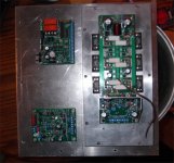
Right on ! (below)
My "beast" badger with 6 - 230W devices and 60V rails did about >40V peak
into a 4R load. Actually loaded down the trafo.
For the forum badger , the semelab 200W devices would be the only alternative
for that same 3 pair setup @ <4R.Both the sanken's and the semelab's have
superior SOA to the ON's @ 60V.
You really DO need that kind of output stage to pass that kind of power !
PS - wolverine is actually a badger ,, it takes a "special species" for torture
on a sub plate amp. (most reliable/stable input stage).
Edit - you actually COULD use the Sanken MT-200's on a badger - the drivers would have to
be out on short leads - but , it could be done. Larger "slug" on the sankens is better at dissipating
heat. Ideal high current devices !
OS
Attachments
Last edited:
Hmmm. Sounds interesting, Ostripper.
Googling amps' insides, I see a lot of Sanken MT200's. Don't know why, maybe they sound especially good? Or something... My current Rotel AVR has them too (1pr/ch). I was wondering if it could be done with the existing board, or that attaching leads to the output transistors would degrade the quality/reliability of the amp in some way. But, after reading your post, I suppose not.
For driving 4 ohm speakers, would you advise using extra-heavy-duty output devices, or should the standard badger be more than be able to deliver the goods - if you don't plan on pi$$ing off the neighbours? As it stands now, I intend to use +/- 56,5V (+/-40V trafo).
Thanks!
I guess it'd be wise to just build the standard amp first. And if I feel like it, I could try to "upgrade" the outputs... Who knows...
Last edited:
- Home
- Amplifiers
- Solid State
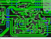
- diyAB Amp The "Honey Badger" build thread