Well, the amp is up and running as it should. I set the bias at 37 mv and after an hour of running my heat sinks are about 30 degrees.
What I found out!
I am blind and an idiot. I put the wrong capacitor in C8, my capacitors measured 4.50pf instead of the 470pf and with my bad eyes, it looked good.
As Pete said if you follow the build guide and it will work. I am so relieved and plan to listen to some music tomorrow. I spent most of the day testing it and finishing the case.
I almost forgot to mention, the 3m pads work nicely and they are easy to use, I have a cheap IR thermometer I bought a couple of weeks ago at harbor freight tools and the battery
was low and giving me erroneous readings, installed a new battery and retested heat sink temperature in use and it was fine.
So it was one wrong value cap. What about these two bad transistors you mentioned?
Good luck with listening tests.
cheers,
Hi Stuart,
Wow, that's complicated.
The only thing I would disagree with is the fan. I have found it much more accurate to have the transistors touching and isolated from local and large air currents. That involves slipping foam over the pair and placing a box over the entire thing. The resulting matches are easily sub 1%. All you need do is go for a null between the collectors using any meter that has an accurate zero. That jig has both PNP and NPN sections and makes use of eight 0.1% resistors. Four for each polarity. You might be able to use 1% parts for the base resistors dropping the count to four 0.1% resistors if you are really tight for cash.
I am very interested in your design. Can you share details with me?
Best, Chris
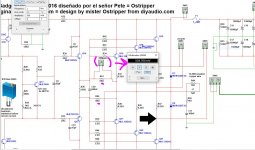
Sure Chris, I don't mind. I'll take note of the fan issue you mentioned and do some testing next time I use it. I also hand picked all of my resistors on this build ensuring all of them were spot on. I must have ordered 200 of each to ensure I go a exact match on all of them. Please find attached a copy of the circuit. I'd be interested in what you think of it.
Attachments
I am using IRFP4668 rated at 10mOhm and 200V because my rails are 70V.
Thank you for this. I also found out the FDP083N15A which a 6.85mohm RDS(on) , but only 150v VDSS though. 150V does not leave sufficient headroom for your 70v rails though, but would be sufficient for the HB's 60v rails :-(
https://www.onsemi.com/pub/Collateral/FDP083N15A-D.pdf
sounding good!
Yes, my eyes are getting worse all the time and I still think sometimes I can work without my glasses.
I received the new transistors and matched them with the Peak Atlas before installing them. I didn't use the old transistors as the Hfe had changed probably due to damage. An expensive lesson which I hope I don't forget
I played the amp in the basement for a couple of days on my Diamond 9.1 speakers and everything sounded great and worked without issue so I moved them upstairs to listen on my Vandersteen's.
This amp is really nice and drives my Vandy's without effort and it's clean and extended. My friend stopped by for a listen and thought I had a subwoofer hiding somewhere in the room. High power and low distortion could become addictive. I put my mono block Millett Uniamps on a shelf and I'm not sure when they will come back out?
So it was one wrong value cap. What about these two bad transistors you mentioned?
Good luck with listening tests.
cheers,
Yes, my eyes are getting worse all the time and I still think sometimes I can work without my glasses.
I received the new transistors and matched them with the Peak Atlas before installing them. I didn't use the old transistors as the Hfe had changed probably due to damage. An expensive lesson which I hope I don't forget
I played the amp in the basement for a couple of days on my Diamond 9.1 speakers and everything sounded great and worked without issue so I moved them upstairs to listen on my Vandersteen's.
This amp is really nice and drives my Vandy's without effort and it's clean and extended. My friend stopped by for a listen and thought I had a subwoofer hiding somewhere in the room. High power and low distortion could become addictive.
I put my mono block Millett Uniamps on a shelf and I'm not sure when they will come back out?Nanchangbob, just looked up Vandersteen. those are expensive, What model do you have?
The top 2 models have built in subwoofers with 400w Amplifier.
You are looking at the higher end Vandersteens which I can not afford.
I have the 2ce signature II, they were expensive to me but they are lower down the Vandersteen line and they don't have the built-in subs, I have always thought about trying a sub on my system but never got around to it.
The Honey Badger does drive these speakers nicely.
Try this oneHi stuartmp,
I get the same error. I'll PM you my email.
-Chris
View attachment matching transistors V3-1mA.pdf
Bias not setting up correctly
Hi all,
I have almost completed building one channel of the honey badger amp. This is what I have done.
1. All components have been installed except the 6 power transistors (Q16 - Q21)
2. I've installed 2 x 68 ohm resistor across R40, R37 to output trace hooked to L1. This was recommended by Pete for the purpose of testing and setting the bias correctly.
3. R30 is set to 550 ohms using a 1k trimmer.
4. R17 is set to centre (500 ohm) of 1k trimmer.
5. R7 is set to around 75ohms using a 200ohm trimmer
Problems in bias adjustment. Reading obtain from Digital Multimeter in DC mV.
a. TP1 and TP2 is giving me around 1mV, no matter how many rounds of R30 (15 turns). No matter I try clockwise or anticlockwise, the voltage stays around 0.8mv to 1mv. Why is this happening? The guide says I must be getting around 20mV - 25mV.
b. When I tested the speaker output using the multimeter in DC mV, the reading keeps changing between 0.7mv to 2.2v. It does not stay still.. it goes up and down and up and down. Is this normal?
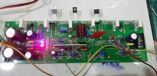
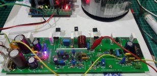
This is how my board has been build for 1 channel. The 2x68 ohm resistor was soldered below the board as described in point 2. above.
Hi all,
I have almost completed building one channel of the honey badger amp. This is what I have done.
1. All components have been installed except the 6 power transistors (Q16 - Q21)
2. I've installed 2 x 68 ohm resistor across R40, R37 to output trace hooked to L1. This was recommended by Pete for the purpose of testing and setting the bias correctly.
3. R30 is set to 550 ohms using a 1k trimmer.
4. R17 is set to centre (500 ohm) of 1k trimmer.
5. R7 is set to around 75ohms using a 200ohm trimmer
Problems in bias adjustment. Reading obtain from Digital Multimeter in DC mV.
a. TP1 and TP2 is giving me around 1mV, no matter how many rounds of R30 (15 turns). No matter I try clockwise or anticlockwise, the voltage stays around 0.8mv to 1mv. Why is this happening? The guide says I must be getting around 20mV - 25mV.
b. When I tested the speaker output using the multimeter in DC mV, the reading keeps changing between 0.7mv to 2.2v. It does not stay still.. it goes up and down and up and down. Is this normal?
This is how my board has been build for 1 channel. The 2x68 ohm resistor was soldered below the board as described in point 2. above.
Attachments
Last edited:
As mentioned you will not be able to adjust the bias until the output transistors have been installed. Using the 68R resistors instead of R36 is bypassing the output section.
The 68R resistors should be connected between the emitter of Q14 or better one side of R36 "electrically the same" and the output trace and do the same thing for Q15, tie a 68R resistor to the other side of R36 to the output trace. If this has been done correctly your dc offset should adjust to less than a millivolt. "mine was anyway" Did you match the input transistors hfe? Even if you didn't it would never go to 2 volts.
I also made sure to install Q13, Q14, and Q15 on the heatsink when I did this test, I'm not sure it's necessary but I'm a worrier.
Check both CCS voltages after you power it up also. Nothing is smoking so that's a good sign.
If these things all check good you need to recheck all your components and make sure you didn't mess up one of them. One wrong capacitor value drove me crazy for a week.
Good luck.
Thanks all for your help.. At least it gives me more confident.. I don't want to blow any of the power transistors as they are not cheap. I'll reply to your feedback one by one. TQ
1. akimmet: Thanks.. gosh.. so I still have to install the power transistors.
2.vargasmongo3435: Juan, thanks a lot for your help. Yes, I was referencing to OS's text. I see.. so I have to measure the voltage across the 68 ohms resistors for 0.55v. Got it.. I will try later.
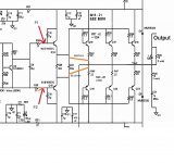
What I did actually was measure from R34 (P1) and R35 (P2) against ground (see circuit attached). I got a +/- 0.9v DC reading on my DMM.... is this normal?
3. nanchangbob: Bob, thanks a lot. You are right.. after installing the 2x68 ohm resistor.. when I measure TP1 and TP2 against ground (without power transistors installed), I got roughly around 1mV-2mV. How much I adjusted R30, the voltage will not go up to 25mV as recommended.
No I didnt measure the hFE on the transistors, but I enclosed them with thermal paste and double layer of shrink tubes.
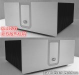
My chassis (see photo attached. The heatsink are part of the chassis) has not arrived yet from China, hence I cannot mount the transistors on the heat sink. I hope it will arrive in 2 weeks time. I am a worrier like you. I worry I will blow up the power transistors.
BTW, I am using the light bulb approach (in series) for the input current into the toroidal transformer. So far the light bulb only lights up for about 2 secs, when powering up and fades away. I believe this is normal as the filter caps are being charged on the PSU.
Thanks... I will continue to post my progress..
BTW, for those who is searching for an affordable pre-amp, good sound and cheap, I will recommend this one from Breeze Audio: Breeze Audio pre-stage Amplifier on Aliexpress.com
1. akimmet: Thanks.. gosh.. so I still have to install the power transistors.
2.vargasmongo3435: Juan, thanks a lot for your help. Yes, I was referencing to OS's text. I see.. so I have to measure the voltage across the 68 ohms resistors for 0.55v. Got it.. I will try later.
What I did actually was measure from R34 (P1) and R35 (P2) against ground (see circuit attached). I got a +/- 0.9v DC reading on my DMM.... is this normal?
3. nanchangbob: Bob, thanks a lot. You are right.. after installing the 2x68 ohm resistor.. when I measure TP1 and TP2 against ground (without power transistors installed), I got roughly around 1mV-2mV. How much I adjusted R30, the voltage will not go up to 25mV as recommended.
No I didnt measure the hFE on the transistors, but I enclosed them with thermal paste and double layer of shrink tubes.
My chassis (see photo attached. The heatsink are part of the chassis) has not arrived yet from China, hence I cannot mount the transistors on the heat sink. I hope it will arrive in 2 weeks time. I am a worrier like you
. I worry I will blow up the power transistors. BTW, I am using the light bulb approach (in series) for the input current into the toroidal transformer. So far the light bulb only lights up for about 2 secs, when powering up and fades away. I believe this is normal as the filter caps are being charged on the PSU.
Thanks... I will continue to post my progress..
BTW, for those who is searching for an affordable pre-amp, good sound and cheap, I will recommend this one from Breeze Audio: Breeze Audio pre-stage Amplifier on Aliexpress.com
Attachments
Last edited:
- Home
- Amplifiers
- Solid State
- diyAB Amp The "Honey Badger" build thread