Good news!
FYI, R53 and R54 should read rail voltage. If you search on the two Badger threads you will see some discussion on them. Some people are in favor of removing them once the amp is set up, because of the fact that they burn instead of the fuse.
Cheers!
280/5000
perfect, I removed them.
After a preliminary adjustment, I switched to listening, I like it!
R14 = 8.24V
Offset = 0.01mV
BIAS = 80mv
after one hour of operation.
How should BIAS be regulated? For now the heatsink is hot but you can hold your hand on ...
thank you.
Page 28/29 of the free build guide offer some tips on this. Assuming you are setting the bias by measuring across TP1/TP2 , 44mV is the highest recommended bias. It is worth noting that hotter doesn't necessarily mean better sounding. It was suggested by some to bias lower with this design to achieve less distortion. This is beyond the level of help I can advise on though ") . I rely on more experienced members for this type of decision.
. I rely on more experienced members for this type of decision.
. I rely on more experienced members for this type of decision.Even as the HB is DIYA's amp , I have been asked to update at least some parts of the BOM. As is the case with many solid state amps , the transistors often become "end of life' or obsolete. TTC004B,Q Toshiba | Mouser The PNP is TTC004B. These are a new product by toshiba , they should be a good sub for the 1381/3503 VAS. KSC2690AYS ON Semiconductor / Fairchild | Mouser KSA1220A is the PNP. Another sub. Keep rails below 65V for these. Sanken and ON have both the drivers and outputs. ANY Sanken TO-3P set will work ANY Sanken TO-220 pair above 160Vceo will also work for drivers. ON is MJE15032/33 to-220 , mouser has many to264/to3p to select. I do not foresee any other changes or discontinued items.
Edit - through-hole will go the same way as Jfets for small to medium signal devices. TO-220 and TO-3p are here to stay because of dissipation requirements. SOT23/223 are what the next badger will have to be. AND with an EF3 OPS ,a 3-4ma VAS that is SOT223 (ZTX957/857).
OS
Edit - through-hole will go the same way as Jfets for small to medium signal devices. TO-220 and TO-3p are here to stay because of dissipation requirements. SOT23/223 are what the next badger will have to be. AND with an EF3 OPS ,a 3-4ma VAS that is SOT223 (ZTX957/857).
OS
Last edited:
Page 28/29 of the free build guide offer some tips on this. Assuming you are setting the bias by measuring across TP1/TP2 , 44mV is the highest recommended bias. It is worth noting that hotter doesn't necessarily mean better sounding. It was suggested by some to bias lower with this design to achieve less distortion. This is beyond the level of help I can advise on though
Sanken's and Fairchild's do best <80ma bias. ON's , right at 100ma.
Different diffusion processes determine this.
OS
...per device
Actually , the real Sankens I have had in a paralleled environment do best at around 50ma.
In HB terms , just 22mv TP1-2.
80-100ma = 36-44mv
Simulation also shows a 3-5 pair OPS , in general .. performs better short of the
optimum bias that just a single pair of devices requires.
Example - performance is the same - 1 pair = 100ma/ 3 pair -75ma / 5 pair 60ma (each).
I have not seen any differences in slewmaster builders results between 50-100ma (besides
more heat).
But , If any feel better running more current/heat because you are
"closer to class A" - knock yourself out. (not over 44MV TP1-2 !!)
OS
Last edited:
Well ... I congratulate for this amp, I built two single channels in a 3U 300mm chassis with 500VA 2x40V toroidal outputs are three pairs MJL4281AG / MJL4302 so regulated:
R14 = 8.24V
OFFSET = 0.01mV
BIAS = 30mV
relatively cool heatshower even after hours of listening, great sound!
Can I say that I have finished and move on to the second channel? I do not hear any audible differences with higher BIAS and I have no tools to verify it.
thank you
R14 = 8.24V
OFFSET = 0.01mV
BIAS = 30mV
relatively cool heatshower even after hours of listening, great sound!
Can I say that I have finished and move on to the second channel? I do not hear any audible differences with higher BIAS and I have no tools to verify it.
thank you
having issue with bias over 20mv
I run the amp and both the small ccs and large ccs are good as well as the DC offset.
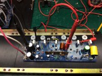
The amp bias will go to about 20mv without any issues and is stable but when I go over 20mv the bias will hit a point and just run and my bulb starts to glow and I need to turn the bias down. I thought because my heatsinks were too large that the Vbe transistor Q13 may not be able to sense properly so I mounted it directly on Q21 as is shown in the photo but it made no difference. I'm sure I must be doing something wrong but I'm not sure what it is?
Both boards respond the same and I'm confused I ordered the 3m 5549s thermal pads to try to help with heat transfer to the sinks and I also attached the datasheet for it.
I've only made it through about half this thread so If it talks about this issue please excuse me and I'm only part way through Mr. Self's power amplifier book and I have read about the output stage yet.
I appreciate any help or thoughts you can share.
I run the amp and both the small ccs and large ccs are good as well as the DC offset.
The amp bias will go to about 20mv without any issues and is stable but when I go over 20mv the bias will hit a point and just run and my bulb starts to glow and I need to turn the bias down. I thought because my heatsinks were too large that the Vbe transistor Q13 may not be able to sense properly so I mounted it directly on Q21 as is shown in the photo but it made no difference. I'm sure I must be doing something wrong but I'm not sure what it is?
Both boards respond the same and I'm confused
I ordered the 3m 5549s thermal pads to try to help with heat transfer to the sinks and I also attached the datasheet for it. I've only made it through about half this thread so If it talks about this issue please excuse me and I'm only part way through Mr. Self's power amplifier book and I have read about the output stage yet.
I appreciate any help or thoughts you can share.
Attachments
bias running!
Thanks for the reply Jan but going across a single resistor instead of the TP's just gives me half the mv reading as it is .22r instead of .45r, I also am not using a load and the input is shorted.
I read about problems with oscillations with the MPSA18's so I switched my LTP to SS9014's and that didn't make any difference. I've looked through the board and I do not see any incorrect value parts, I was pretty careful.
The thing is it has correct ccs voltages and they are stable also the dc offset is good, it only goes off when with bias starts to run, one channel runs at about 20mv and the other one runs off at about 14mv, up to that point it seems perfectly normal. I would really like to set the bias to at least the 50ma which is recommended which I believe would be around 22mv across the tp's?
This is my first large solid state amp and things went well until now.
Does anyone have any suggestions I might check or try? I'm truly perplexed.
Thanks,
Bob
Thanks for the reply Jan but going across a single resistor instead of the TP's just gives me half the mv reading as it is .22r instead of .45r, I also am not using a load and the input is shorted.I read about problems with oscillations with the MPSA18's so I switched my LTP to SS9014's and that didn't make any difference. I've looked through the board and I do not see any incorrect value parts, I was pretty careful.
The thing is it has correct ccs voltages and they are stable also the dc offset is good, it only goes off when with bias starts to run, one channel runs at about 20mv and the other one runs off at about 14mv, up to that point it seems perfectly normal. I would really like to set the bias to at least the 50ma which is recommended which I believe would be around 22mv across the tp's?
This is my first large solid state amp and things went well until now.
Does anyone have any suggestions I might check or try? I'm truly perplexed.
Thanks,
Bob
Are your power transistors, driver and bias transistor genuine? Is there a good thermal connection between each transistor and the heatsink? Is there a good thermal connection between bias transistor and the heatsink/power transistors? Have you matched power transistors?
I had such a problem once and power transistors were to blame.
cheers,
I had such a problem once and power transistors were to blame.
cheers,
All the parts are from digikey so I assume they are the real deal, I have tried the expensive 3m pads and the normal pink silicone pads and it makes no difference I also made sure they are secured well to the heat sink.
I only matched hfe on the input LTP, cascode and current mirror transistors I can't fit the outputs in my dmm. I was considering picking-up a peak atlas IT, I just didn't see anyone having an issue like this with this build and thought the outputs would be alright.
I also had the same worry about heat transfer as the heatsinks I am using are really large and I can't tell if there heating up because there is no real temperature change. I even took the time to drill and tap some smaller heat sinks just to make sure and everything behaved the same.
It certainly seems like the outputs are going into run away at a fairly low bias point and the fact it acts perfectly normal until I try to push them a little higher has me scratching my head.
I do not know Peak atlas IT. I know one that it's designed to test cables so there must be some other Peak Atlas. DMM will not help you much with power transistors as these have to be tested at higher currents. I use DY294.
Thermal runaway is also possible when there are large parameter (Vbe and gain) discrepancies between transistors but if transistors came from the same batch it's less likely. If you have a few leftover transistors you might check their gain and Vbe. You can read here about matching: Matching Power and Driver Transistors
If all your transistors are OK (which is not necessarily the case) then there must be something wrong somewhere else. Did you measure each resistor and capacitor before mounting? There are no miracles, it's either some faulty component or a mounting error.
When your bias starts to grow does the zoebel resistor get warm?
It also could be board flaw - the least likely but some hairlike invisible connection or invisible broken track can be very difficult to spot but bring nasty consequences.
good luck,
I actually have a DY294 transistor tester I bought when I lived in China but it died. Anyway, I went ahead and bought the Peak Atlas tester and it will arrive tomorrow.
PEAK Atlas Atlas IT (DCA Pro) ADVANCED SEMICONDUCTOR ANALYZER with Curve Tracing: Amazon.com: Industrial & Scientific
I checked the capacitors and even matched resistors for this build, as I mentioned I was very careful.
Today I removed the outputs and installed the 68r resistors and removed R36 as Pete suggested and it worked as it should, I even passed a 1khz signal through it and it had a nice clean signal out.
I actually had another order from mouser which I ordered some items and I ordered one set of outputs in case something went wrong. I will check them with the Peak atlas and compare them to the outputs I removed that I received from Digikey.
I have ordered from Digikey a number of times through the years and I never received anything defective from them, but these outputs work just fine until I try to push them, I really don't know what else it could be. I'll let you know what I find out.
This is one of the nightmares we pray not to encounter. Nevertheless, there is something wrong with some components as the design is fine.
What about emitter resistors? Are they non-inductive? Standard metalised emitter resistors and large variation in power transistor parameters may cause oscillation when driven harder. With mosfets I use non-inductive gate resistors but with bjts it's going overboard.
Thanks for the link. Interesting model. I have older dca 55 (not so many functions) but I see that both use too small current for testing and matching power transistors. You can build a test circuit as shown in Elliot's article. It won't fail (resistors are easily replaceable) and it allows for large enough current testing. I would say that still number one suspect would be at least one of the power transistors failing at higher currents if all the other are fine.
Please let us know as it might happen to anyone. So far no one had this kind of a problem with Honey Badger.
good luck,
PS there was such a problem with some Diamond amp builds (there is a thread somewhere here) and the problem was VAS oscillation, which could be solved by using certain components and some mods but in HB VAS design is fine.
PS 2 Do you have one HB board not yet populated? Populating it and testing each stage could provide some clues.
PS 3 a comment made by one of the Atlas dca 75 pro users. Might apply to your case.
3. When testing a house numbered transistor I used an old reliable go/no go transistor tester with a amplification indicator lamp. In one instance for example; I could get a particular house numbered transistor to only function at a narrow window of current setting. Others with the same exact house numbers would amplify over a board range of current since I can vary it, in this case it might be safe to assume this is how these unknown transistors should amplify is at the broader range of current, at least with these anyway. Anyway, the DCA 75 doesn't say that the transistor is marginal or weak, when I think it likely is?
Last edited:
- Home
- Amplifiers
- Solid State
- diyAB Amp The "Honey Badger" build thread