Thanks a lot..sounds like a great idea since all 3 pairs are equal. Do you think I can try this without attaching the power transistors to the heatsink? Can I just apply a little solder like what Juan mentions but transistor is clinging to the PCB in the air. Also I have to remember to remove the 2x68ohm resistors n install the R36 resistor.
My chassis is still shipping hence no chance to use the heatsinks yet.
My chassis is still shipping hence no chance to use the heatsinks yet.
Thanks a lot..sounds like a great idea since all 3 pairs are equal. Do you think I can try this without attaching the power transistors to the heatsink? Can I just apply a little solder like what Juan mentions but transistor is clinging to the PCB in the air. Also I have to remember to remove the 2x68ohm resistors n install the R36 resistor.
My chassis is still shipping hence no chance to use the heatsinks yet.
use claps to a heat sink with a bit of heat sink compund and all insulated with mica or rubber insulator maybe you can use a aluminum bar to secure all of them and bias transistor to the maing heat sink sorry about the ugly drawig something like this
Attachments
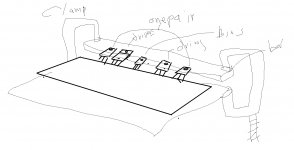
oh I see do you have any aluminum that you can use? a 1/8" thick large sheet aluminum plate maybe? if you don't have any way to cool down the semiconductors you should wait there is no rush on this things don't adjust bias if you don't have proper dissipation device heat sink just wait till you get you heat sinks
Thanks a lot..sounds like a great idea since all 3 pairs are equal. Do you think I can try this without attaching the power transistors to the heatsink? Can I just apply a little solder like what Juan mentions but transistor is clinging to the PCB in the air. Also I have to remember to remove the 2x68ohm resistors n install the R36 resistor.
My chassis is still shipping hence no chance to use the heatsinks yet.
Just not doing this!
Don't try anything without a heatshink.
You can solder using a little of solder but make sure that the solder point isn't a cold solder.
Last edited:
We often see construction where transistors are solder to PCB before attaching transistor to heatsink, according to me it should not be done this way .... leads should be bended as needed, transistors bolted on heatsink, PCB put in place ( with bolts, spacers and nuts ) then the last thing to do is solder, this way there will be no stress on the solder and PCB pads.
Hi Guys,
This is a diagram from Bob Cordell's book. It show the power gnd, speaker return gnd, and signal gnd. All extending from the star ground.
Can someone please explain to me why the HB has the speaker return gnd is going to the same point on the HB amplifier board as the power gnd.
Won't you get less noise on the speaker return ground if it went directly back to the star ground?
Last edited:
and if it's a dual mono or mono Block, the star gnd will be on the amp board.
My builds are usually dual mono and I always return the speakers to the respective power supply.
My builds are usually dual mono and I always return the speakers to the respective power supply.
well. when each ch has it's own supply, it's not needed. but it can't hurt.
also. i have build a few dual mono's. and if you have the star gnd on the psu or the amp board has never done anything positive or negative. atleast as long as you seperate the Earth ground for each ch..
i'm now planning a 5ch honey badger on common PSU. there i'm gonna gnd all speaker returns to the PSU")
i'm now planning a 5ch honey badger on common PSU. there i'm gonna gnd all speaker returns to the PSU
Last edited:
My builds are usually dual mono and I always return the speakers to the respective power supply.
this is what i did with my first super leach amp in 1994, i never looked back and did things differently....
the rationale for putting the speaker ground return wire direct to psu cap junctions is because of all wires carrying current, this speaker wires have the potential of carrying the biggest current. so that if this wire is connected to the board ground instead, the resulting drop from that wire can possibly shift the ground some...not good...whereas if the board ground wire is left alone, the there is a constant ground reference unaffected by changes in speaker power outputs...
I think that returning the speaker gnd to PSU gnd directly is of even more importance if bridging is intended or at least it's possibility is given.
But then, how do you twist the speaker leads? Just right down to the amp PCB and let the gnd wire alone run to the PSU?
Best regards!
But then, how do you twist the speaker leads? Just right down to the amp PCB and let the gnd wire alone run to the PSU?
Best regards!
- Home
- Amplifiers
- Solid State
- diyAB Amp The "Honey Badger" build thread