The TCA955 chip is still available from several vendors. Attached clip is its use as controller in a Thorens TT.
The circuit is for a DC motor with a tachymetric generator.
It seems to be a chopper.
Ist it possible, with the K&K supply, to regulate the phase shift between the two phases
Yes. It has two separate outputs with phase trim. This requires rewiring the motor with a new power cord and removing the cap from the motor pod.
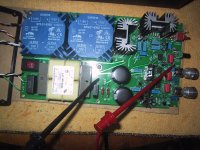
Attachments
Somehow, this thread got terribly off topic. The OP was to see if there was interest in doing a group buy based on an already designed and CADed turntable power supply. The thread has turned into a design session on which topology is the best to use, from digital synthesizers to class A tube amp outputs. All of these have been discussed in other threads.
True, the current design is not very sophisticated or clever. It is not a commercial product, but an easy to build DIY design. Sure, it could be made better in a lot of ways, but unless someone wants to redesign it, it is what we are stuck with.
So back to the original purpose of this thread:
If enough people are interested in building this project, could someone with group buy experience work out the details to have the boards made?
I think the most that had seen this threat would'nd work with the XR Chip cause it is not stable enough for a good turntable supply. My opinion is that it will be better to work out a good sinus/cosinus generator an then make a group by out of it.
Second i think that the XR chip based oszillater dont need a special PCB. It is so simple that you can build it on an universal board without problems. It needs a really very simple design that can be taken out of the datasheet.
Regards
Dieter
Second i think that the XR chip based oszillater dont need a special PCB. It is so simple that you can build it on an universal board without problems. It needs a really very simple design that can be taken out of the datasheet.
Regards
Dieter
Last edited:
- Status
- This old topic is closed. If you want to reopen this topic, contact a moderator using the "Report Post" button.