Hi,
Your question has been answered several times in this thread. Might be taking too much time to look it up, so:
When your current arrangement shows unstable behaviour, you could
1: use smaller diameter magnets(height needs to remain the same)
2: attach the thread farther up, relative to the lower magnet. In other words, raise the attachment point of the thread
3: (not recommended) use a counterweight with a lower center of gravity(relative to the bearing level)
Other options do exist, but the above seem to be within your reach.
Don't give up and
good luck!
Frank
thank you.
options one and two would involve digging out the magnet and washer which would ruin the arm I believe (they got glued in good). I did imagine the glue in magnet being a problem and so i turned an extra arm prior....I have yet to drill and mount mags and washer however.......I may try option 3....there was no counterweight btw in my testing. But in my arm#1 I didn't have this problem even without counterweight....I did use .5" magnets in arm 1 and used .7 in arm #2. I also lowered the anchoring point in arm #2. Both the larger mags and lower mount where desirable according to what I read. Them potentially leading to this instability, I had not read......I really wonder how you guys succeeded. You must have hawk eyesight and patience beyond measure.!
besides rega250 , I am looking at jelco370 if anyone has any thoughts on that arm? i've got to get an arm on my lenco l70.....carts are stant0n881 and shurev15III. both are high compliance and jelco wants medium so.....I'd like to try it regardless as I've already owned 3 rega arms and they 'have a sound'. I like them but.... thanks in advance
Last edited:
I really wonder how you guys succeeded.
We are geniuses.
An externally hosted image should be here but it was not working when we last tested it.
Hi again,
you wrote:
"Both the larger mags and lower mount where desirable according to what I read."
By "lower mount" I assume you mean a lower attachment point for your thread. Lower than what you might have had(a bearing with a high restoring force) is better until you go past the point where the bearing acts as a neutral balance bearing(that's when it becomes unstable). In other words: you CAN pick too low an attachment point.
Larger mags can mean larger diameter or larger height(thickness). Both have a diametrically opposed effect. All other things being the same: Larger diameter: less stable balance, larger thickness: increased stability
You have to pick the right magnet size ratio AND attachment point. That has nothing to do with eyesight or being a genius.
Cheers,
Frank
is there any issue with using 2 RING magnets rather than 2 disc magnets?
ring magnets have what is called - parallel magnetic field
I ask because I need the center hole to attach the magnets......Cannot do press fit and would rather not epoxy them in (and these seem to be the only 3 choices in attaching the magnets)
Another option is to use a disc magnet but place it in a thing called a magnet cup that both increases pull and also give a way to attach....One could screw or glue the cup in (arm or lower section) and then put the magnet in the cup....I read that should one cut a small gap along the side prior to install, one could then pry the magnet out should he want to remove the magnet....
http://www.ebay.com/itm/2-Neodymium...071558?hash=item2a768543c6:g:GmEAAOSwa~BYRGcH
ring magnets have what is called - parallel magnetic field
An externally hosted image should be here but it was not working when we last tested it.
I ask because I need the center hole to attach the magnets......Cannot do press fit and would rather not epoxy them in (and these seem to be the only 3 choices in attaching the magnets)
Another option is to use a disc magnet but place it in a thing called a magnet cup that both increases pull and also give a way to attach....One could screw or glue the cup in (arm or lower section) and then put the magnet in the cup....I read that should one cut a small gap along the side prior to install, one could then pry the magnet out should he want to remove the magnet....
http://www.ebay.com/itm/2-Neodymium...071558?hash=item2a768543c6:g:GmEAAOSwa~BYRGcH
Last edited:
this explanation is what I googled- seems like this would make a ring magnet have less pulling power compared to a disc?
:
"If the external upper edge is North, then the internal (near hole) upper edge is South, and vice versa. (And the same thing holds for the other edge.) So along an axis, you have North-South-North-South in this order rather than North-North-South-South."
:
"If the external upper edge is North, then the internal (near hole) upper edge is South, and vice versa. (And the same thing holds for the other edge.) So along an axis, you have North-South-North-South in this order rather than North-North-South-South."
Hi Plexi,
The picture does not accurately depict the fluxline distribution on a ring magnet with axial magnetisation. Nevertheless, such(N-S axial) ring magnets can be used. The required dimensions will differ quite a bit from "same" size(height x diameter) disc magnets(all other bearing dimensions:attachment point, gap width, etc... being the same).
The potted magnets in your ebay link are very much usable. Same caveat as above.
A HAPPY AND HEALTHY 2017 to all!
Frank
Last edited:
These are smaller, easier to install.
10 Large 1/2 x 1/4 inch Neodymium Disc Magnets Super Strong Rare Earth Magnet | eBay
10 Large 1/2 x 1/4 inch Neodymium Disc Magnets Super Strong Rare Earth Magnet | eBay
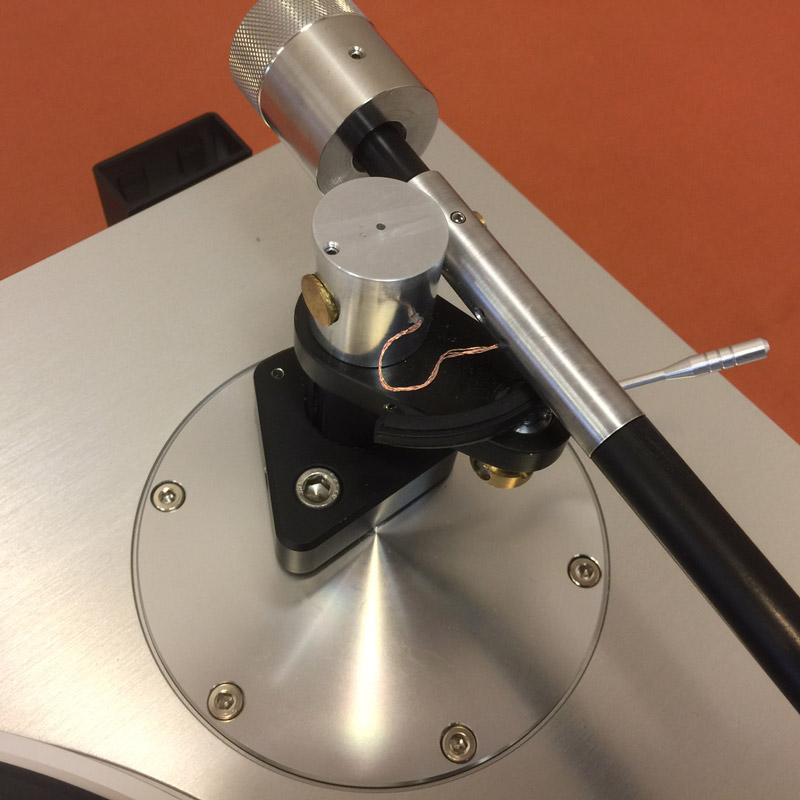
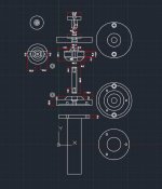
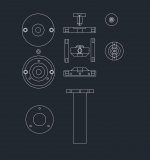
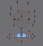
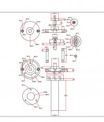
so, my plan is to use an approx 1" ring magnet in the bottom section and a 5/8" cupped disc magnet in the top (arm) since the cupped disc should be considerably stronger than a ring magnet (as per berlineta's last post)......I am doing this because I cannot easily get 2 ring magnets that have opposing poles, so In order to be able to screw the ring magnet in and screw the upper magnet, it will be easier when the top magnet is a cupped disc. I am planning the cup being a male threaded cup that will go into the arm approx 1/4" then right above that (still lower 1/2" in arm) I may drill a horizontal hole that goes across the arm. In that hole I will slip a 1mm metal piece (say drill bit section) and it will go through a threaded hole in the suspension line.....The same will happen up top at upper most bias screw/mounting point.
should anyone understand my drawing yet see an issue, please let me know,thanks
it's not easy to explain or visualize how this suspension thread will atatch to the 1mm metal pin but the above pics are what I'm aiming at..it may not even work it's hard to tell until I try and try and attach the thread to the pin....
but the idea is to drop the suspension line down through the arm (the line will have a loop in it) where the 1mm metal pin will go through and be captured by the loop. That may be the tricky part - sliding the pin through the suspension line hole....With this arrangement I can then screw in the male threaded magnet cup and service it at any time should the need arise....but the main reason is because I cannot press the magnets in and would rather not glue. SO screwing them in seems my only option (screw bottom mag directly in and screw the male cupped magnet in arm) then press the disc magnet in that cup...
http://www.ebay.com/itm/CMS-Magneti...hash=item4af2667955:m:mn5mhqG3Hma9J27C3hd26Pw
btw, the reason I'm not just using a knot in the suspension thread at the bottom as an anchor solution is because I am unable to drill a small enough hole and/or create a good knot in my thread..this is why I'm trying to use the horizontal metal pin idea
should anyone understand my drawing yet see an issue, please let me know,thanks
An externally hosted image should be here but it was not working when we last tested it.
An externally hosted image should be here but it was not working when we last tested it.
An externally hosted image should be here but it was not working when we last tested it.
An externally hosted image should be here but it was not working when we last tested it.
photo shareit's not easy to explain or visualize how this suspension thread will atatch to the 1mm metal pin but the above pics are what I'm aiming at..it may not even work it's hard to tell until I try and try and attach the thread to the pin....
but the idea is to drop the suspension line down through the arm (the line will have a loop in it) where the 1mm metal pin will go through and be captured by the loop. That may be the tricky part - sliding the pin through the suspension line hole....With this arrangement I can then screw in the male threaded magnet cup and service it at any time should the need arise....but the main reason is because I cannot press the magnets in and would rather not glue. SO screwing them in seems my only option (screw bottom mag directly in and screw the male cupped magnet in arm) then press the disc magnet in that cup...
http://www.ebay.com/itm/CMS-Magneti...hash=item4af2667955:m:mn5mhqG3Hma9J27C3hd26Pw
btw, the reason I'm not just using a knot in the suspension thread at the bottom as an anchor solution is because I am unable to drill a small enough hole and/or create a good knot in my thread..this is why I'm trying to use the horizontal metal pin idea
Last edited:
so I was able to capture the 1mm steel pin with the thread but am having issues tying the top not. Need to research on what kind of knot to use at that point.....this is just a mock up, still no magnet in arm but everything is nice and centered so I think this may work >?
An externally hosted image should be here but it was not working when we last tested it.
image uploadhttps://www.youtube.com/watch?v=lot03DTdLlU&feature=youtu.be
can anyone help on this. there is too much downward pressure on the cart side. I think it's because the string being wrapped around that pin. Is this a totally useless method or is there a way to salvage by manipulating the string's attachment method? any ideas appreciated.
can anyone help on this. there is too much downward pressure on the cart side. I think it's because the string being wrapped around that pin. Is this a totally useless method or is there a way to salvage by manipulating the string's attachment method? any ideas appreciated.
realized I needed to tie two noose knots on each end. this keeps it centered. this feels pretty good. if anyone sees why this shouldn't work please advise ! thanks
ture hosting
An externally hosted image should be here but it was not working when we last tested it.
picAn externally hosted image should be here but it was not working when we last tested it.
upload pictures freeture hosting
Last edited:
My magnetic pull pivot tonearm
Here's my try one magnetic pull pivot tonearm
https://www.facebook.com/photo.php?fbid=10155274224348669&set=o.1689741724600319&type=3&theater
The one on your right. Left one is simple unipivot one.
Here's my try one magnetic pull pivot tonearm
https://www.facebook.com/photo.php?fbid=10155274224348669&set=o.1689741724600319&type=3&theater
The one on your right. Left one is simple unipivot one.
realized I needed to tie two noose knots on each end. this keeps it centered. this feels pretty good. if anyone sees why this shouldn't work please advise ! thanks
An externally hosted image should be here but it was not working when we last tested it.pic
An externally hosted image should be here but it was not working when we last tested it.upload pictures free
ture hosting
First think I would replace the counter weight. That aluminium not the best idea. People use Tungsten or other hard materials, also that would reduce the size of it.
") Even if you use iron or brass would be an upgrade. That would reduce the size, On your second picture the counter weight touches the base of the suspension. please pay att. to that
Even if you use iron or brass would be an upgrade. That would reduce the size, On your second picture the counter weight touches the base of the suspension. please pay att. to that
Last edited:
New Schroeder tonearm
Some new designs still are coming from Frank.
The Alto tone arm - Designed by Frank Schroder | Soundsmith
I wonder, what advantages of asymmetrical loading are. Is skating force still present? If yes, is it managed somehow?
As always with Frank arms, it is a beauty...
Some new designs still are coming from Frank.
The Alto tone arm - Designed by Frank Schroder | Soundsmith
I wonder, what advantages of asymmetrical loading are. Is skating force still present? If yes, is it managed somehow?
As always with Frank arms, it is a beauty...
ALTO
From the horse mouth or Frank's mouth.
I wonder, what advantages of asymmetrical loading are. Is skating force still present? If yes, is it managed somehow?
As always with Frank arms, it is a beauty...
From the horse mouth or Frank's mouth.
2nd project
I always loved the DIY tonearm schroeder style ... magnet bearing on the pivot , give a damper maximum effect and friction free.
My 2nd project of that was inspired from web_ Magnetico from Attitube
and i used Carbon fiber from fisinh rod, and in my opinion this was a good resulted.
Album - Google+
[IMGDEAD]https://lh3.googleusercontent.com/-Ymr31Fbwem0/WBhgJjhnOaI/AAAAAAAATPQ/VvkZjDk_41w542pLE41UMtvwQQAQrlANACJoC/w663-h1178-p-rw/16%2B-%2B1[/IMGDEAD]
[url]https://lh3.googleusercontent.com/-j3EVRftRw9I/WANWyM9hoHI/AAAAAAAAS1k/0ulrVCdEMMciZhqpA_1CAqxzKFDIx7GtwCJoC/w492-h398-n-rw/16%2B-%2B3[/url]
detail on pic
[url=https://youtu.be/dQz0pySTL3s]MY DIY Tonearm project on G+ - YouTube[/url]
I always loved the DIY tonearm schroeder style ... magnet bearing on the pivot , give a damper maximum effect and friction free.
My 2nd project of that was inspired from web_ Magnetico from Attitube
and i used Carbon fiber from fisinh rod, and in my opinion this was a good resulted.
An externally hosted image should be here but it was not working when we last tested it.
Album - Google+
[IMGDEAD]https://lh3.googleusercontent.com/-Ymr31Fbwem0/WBhgJjhnOaI/AAAAAAAATPQ/VvkZjDk_41w542pLE41UMtvwQQAQrlANACJoC/w663-h1178-p-rw/16%2B-%2B1[/IMGDEAD]
[url]https://lh3.googleusercontent.com/-j3EVRftRw9I/WANWyM9hoHI/AAAAAAAAS1k/0ulrVCdEMMciZhqpA_1CAqxzKFDIx7GtwCJoC/w492-h398-n-rw/16%2B-%2B3[/url]
detail on pic
[url=https://youtu.be/dQz0pySTL3s]MY DIY Tonearm project on G+ - YouTube[/url]
Last edited:
2nd project
I always loved the DIY tonearm schroeder style ... magnet bearing on the pivot , give a damper maximum effect and friction free.
My 2nd project of that was inspired from web_ Magnetico from Attitube
and i used Carbon fiber from fisinh rod, and in my opinion this was a good resulted.
Hi suwaned,
I really liked your approach, since every part can be constructed using a lathe (I own a lathe but, unfortunately, I don't have a mill yet). I also watched you video on youtube - great job!
Could you please send me the drawings that I saw in your video? It would be of great help.
Regards,
Evangelos
Hello,
thank you for your appreciation.
for parts of TA can be using by Lathe, this is awesome circular construction ( helpfull for lathe) of Magnetico _Attitube. for headsheal need a mil, but this not fixed.
i have a drawings of my project, but this is not fixed because there are parts that I adjust to the existing constraints at done, error and try ... some parts 3 times do it.
Best Regards
ed suwan
my DIY Audio Project"s - Google+
Attachments
Last edited:
- Home
- Source & Line
- Analogue Source
- DIY Schroeder Tonearm???