Some help:
"Length/Width/Thickness of magnet" is the length/width/thickness of each individual magnet. Magnetization, in this program, is always through the thickness value.
The "Distance between magnets" is the gap where the ribbon is situated.
"Input resistor" is for when the Diy:er puts a resistor in series with transformer or the ribbon track(s) itself.
"Strength of magnet" is the core strength of a neodymium magnet, often called "Br" in the manufacturers specifications, and is usually around 1.2 to 1.4 Tesla (12000 to 14000 Gauss).
"Iron Yoke" have to be ticked if the magnets are mounted in a non saturated
iron loop assembly.
Gerrit,
Congratulations on one of the finest DIY tweeters I have ever seen. I was just about to embark on my own ribbon making journey and thought I would see if anyone has already done it for lessons learned. Yours is up there with the best money could buy. Congratulations on the excellent result and thanks for great documentation and sharing. I like your magnet pole design and think that is key to why this works so well. When looking at post one I thought to myself "those magnets don't want to be like that!" So thanks for showing the clamping tricks and jigs and guides needed to accomplish it.
I have a bunch of rectangular flat Nd magnets already. How do I check to see if poles are laid out as you have?
What do you use to glue magnets to wooden frame strip spacer?
Thanks.
Thanks for the great complimentGerrit,
Congratulations on one of the finest DIY tweeters I have ever seen. I was just about to embark on my own ribbon making journey and thought I would see if anyone has already done it for lessons learned. Yours is up there with the best money could buy. Congratulations on the excellent result and thanks for great documentation and sharing. I like your magnet pole design and think that is key to why this works so well. When looking at post one I thought to myself "those magnets don't want to be like that!" So thanks for showing the clamping tricks and jigs and guides needed to accomplish it.
I have a bunch of rectangular flat Nd magnets already. How do I check to see if poles are laid out as you have?
What do you use to glue magnets to wooden frame strip spacer?
Thanks.
")
If your magnets stick together like on this picture:

you're OK.
I used epoxy resin glue (10 minute) for the wood frame, on the brass frame this did not work well so there I used PU resin glue (they grey stuff). In hindsight I would advise epoxy resin glue with a longer cure time because this will result in a stronger bond.
I'm very happy with my ribbon tweeters, both in the main channels and the surround speakers, they are extremely 'easy on the ears'. The music doesn't sound reproduced, it's just there. Using this system for almost a year I still consider it a blameless loudspeaker (as far as such a thing is possible given the compromises inherent in the design). With my previous systems there was always something that wasn't quite right, usually this starts after a couple of months of listening, not this time
regards,
Gerrit
Thanks for the great compliment
If your magnets stick together like on this picture:
View attachment 523526
you're OK.
I used epoxy resin glue (10 minute) for the wood frame, on the brass frame this did not work well so there I used PU resin glue (they grey stuff). In hindsight I would advise epoxy resin glue with a longer cure time because this will result in a stronger bond.
I'm very happy with my ribbon tweeters, both in the main channels and the surround speakers, they are extremely 'easy on the ears'. The music doesn't sound reproduced, it's just there. Using this system for almost a year I still consider it a blameless loudspeaker (as far as such a thing is possible given the compromises inherent in the design). With my previous systems there was always something that wasn't quite right, usually this starts after a couple of months of listening, not this time
regards,
Gerrit
Hmm the picture of the Magnets Dont say much about the magnet direction
trough thicknes can lay like this if I remember correctly your magnets where not the most standard magnets direction(trough thickness) every magnet direction I can think of could make up this picture trough width , height and thickness , which one you used ?Thanks for the great compliment
If your magnets stick together like on this picture:
View attachment 523526
you're OK.
I used epoxy resin glue (10 minute) for the wood frame, on the brass frame this did not work well so there I used PU resin glue (they grey stuff). In hindsight I would advise epoxy resin glue with a longer cure time because this will result in a stronger bond.
I'm very happy with my ribbon tweeters, both in the main channels and the surround speakers, they are extremely 'easy on the ears'. The music doesn't sound reproduced, it's just there. Using this system for almost a year I still consider it a blameless loudspeaker (as far as such a thing is possible given the compromises inherent in the design). With my previous systems there was always something that wasn't quite right, usually this starts after a couple of months of listening, not this time
regards,
Gerrit
I was afraid of that. Mine naturally stick big flat to flat. Pole oriented along shortest distance (thickness).
Is there anyway to get a magnet like that to work? I suppose I could rotate it 90 but it then makes a deep resonance channel.
I was afraid of that. Mine naturally stick big flat to flat. Pole oriented along shortest distance (thickness).
Is there anyway to get a magnet like that to work? I suppose I could rotate it 90 but it then makes a deep resonance channel.
That's the most common , flip one over and you have the picture
.It's indeed confusion, maybe look at rj magnetics they have some info
Here're the specifications used for the order:

Magnetisation direction is through the 10mm axis. The top view is for the steel frame ribbon:

In the US this type of magnet is readily available:
K&J Magnetics: BX024 although these are not as thin and strong as the ones I used.
regards,
Gerrit
Magnetisation direction is through the 10mm axis. The top view is for the steel frame ribbon:
In the US this type of magnet is readily available:
K&J Magnetics: BX024 although these are not as thin and strong as the ones I used.
regards,
Gerrit
Here're the specifications used for the order:
View attachment 523532
Magnetisation direction is through the 10mm axis. The top view is for the steel frame ribbon:
View attachment 523533
In the US this type of magnet is readily available:
K&J Magnetics: BX024 although these are not as thin and strong as the ones I used.
regards,
Gerrit
that looks beautiful !
that looks beautiful !
Thanks for the compliment
Here's a drawing with dimensions and a simulation of the magnetic flux density:

The frames were made by someone else, I don't have machinery to mill steel.
regards,
Gerrit
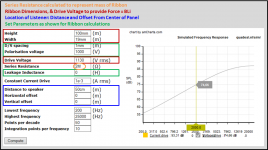
I've put together a small program based on the "Simple Ribbon Equations" found here: http://www.diyaudio.com/forums/planars-exotics/50162-another-diy-ribbon-thread-55.html
Thanks for the program, the magnetic field plotter is very nice.

I’m not sure about the SPL calculation portion…it seems the equations were developed based on the same methodology used for dynamic drivers. The assumptions of 1) infinite baffle, 2) point source, and 3) mass of radiator >> mass of air load that are implicit in the equation don’t seem to match the reality of dipole ribbon speakers very well.
A thought occurred to me while driving home
 …
…The same reciprocity argument used to develop the Walker Equation that works so well for ESL modeling should apply for deriving a similar expression for ribbon speakers. In fact…forget the derivation, just replace the parameters representing “Total Force” in the Walker equation with (B*L*i) for the ribbon!
P = (B*L*i*f)/(2*c*r)
SPL = 20*LOG(P/Po)
P = pressure (N/m^2)
Po = reference pressure = 2e-5 (N/m^2)
B = flux density (Tesla)
L = length of ribbon (m)
i = current thru ribbon (Amp)
c = speed of sound = 343 (m/s)
r = distance from ribbon (m)
Assumption:
1) massless, uniformly driven, dipole ribbon
2) distance from ribbon is far enough that it behaves like a point source
3) minimal baffle surrounding ribbon
The best test case I could think of was the ribbon that started this thread since Gerrit has provided complete information for it:
- Dimensions provided in post #1
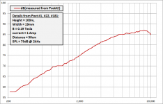
- Frequency response measurement provided in post #2
- Flux density measurement provided in post #181
- SPL level measurement provided in post #22
Combining all this information results in the attached pic.
OK, let’s try out the equation at the 2kHz test frequency from post#22 (75dB @ 50cm for 1 amp current)
P = [(0.19)(0.1)(1)(2000)] / [(2)(343)(0.5)] = 0.11 N/m^2
SPL = 20LOG(0.11/2e-5) = 74.8dB !!!
Looking again at the attached pic, note that the SPL increases proportional to frequency (ie +6dB/oct) over most of the audio range just like the formula would indicate. However, the top two octaves are flattened due to the mass of the ribbon which is not accounted for in the formula (ie assumption 1 not met). For measurement of essentially massless ribbon, see post #122. Also, if the ribbon was longer (>1m) I would expect to see additional flattening and some ripples in the response similar to ESLs. (ie assumption 2 not met)
It occurred to me while typing in this response that we could get around assumption 2 by using a generalized form of the Walker equation as is done in the ESL simulator:
Electrostatic Loudspeaker (ESL) Simulator
http://www.diyaudio.com/forums/planars-exotics/258958-help-esl-simulator.html#post3986989
Hmmmmm....
 In fact, we could just use the ESL simulator directly by determining ESL parameters to use that represent the ribbon parameters. The roll off due to ribbon mass could also be modeled using the series resistance parameter in the ESL simulator. I will give this a try and post results later tonight.
Attachments
WowThanks for the program, the magnetic field plotter is very nice.
I’m not sure about the SPL calculation portion…it seems the equations were developed based on the same methodology used for dynamic drivers. The assumptions of 1) infinite baffle, 2) point source, and 3) mass of radiator >> mass of air load that are implicit in the equation don’t seem to match the reality of dipole ribbon speakers very well.
A thought occurred to me while driving home
The same reciprocity argument used to develop the Walker Equation that works so well for ESL modeling should apply for deriving a similar expression for ribbon speakers. In fact…forget the derivation, just replace the parameters representing “Total Force” in the Walker equation with (B*L*i) for the ribbon!
P = (B*L*i*f)/(2*c*r)
SPL = 20*LOG(P/Po)
P = pressure (N/m^2)
Po = reference pressure = 2e-5 (N/m^2)
B = flux density (Tesla)
L = length of ribbon (m)
i = current thru ribbon (Amp)
c = speed of sound = 343 (m/s)
r = distance from ribbon (m)
Assumption:
1) massless, uniformly driven, dipole ribbon
2) distance from ribbon is far enough that it behaves like a point source
3) minimal baffle surrounding ribbon
The best test case I could think of was the ribbon that started this thread since Gerrit has provided complete information for it:
- Dimensions provided in post #1
- Frequency response measurement provided in post #2
- Flux density measurement provided in post #181
- SPL level measurement provided in post #22
Combining all this information results in the attached pic.
OK, let’s try out the equation at the 2kHz test frequency from post#22 (75dB @ 50cm for 1 amp current)
P = [(0.19)(0.1)(1)(2000)] / [(2)(343)(0.5)] = 0.11 N/m^2
SPL = 20LOG(0.11/2e-5) = 74.8dB !!!
Looking again at the attached pic, note that the SPL increases proportional to frequency (ie +6dB/oct) over most of the audio range just like the formula would indicate. However, the top two octaves are flattened due to the mass of the ribbon which is not accounted for in the formula (ie assumption 1 not met). For measurement of essentially massless ribbon, see post #122. Also, if the ribbon was longer (>1m) I would expect to see additional flattening and some ripples in the response similar to ESLs. (ie assumption 2 not met)
It occurred to me while typing in this response that we could get around assumption 2 by using a generalized form of the Walker equation as is done in the ESL simulator:
Electrostatic Loudspeaker (ESL) Simulator
http://www.diyaudio.com/forums/planars-exotics/258958-help-esl-simulator.html#post3986989
Hmmmmm....

Amazing how the theory matches reality.
regards,
Gerrit
The match was much better than I had anticipated…it could be due to your careful measurements, or maybe just a happy coincidence.Amazing how the theory matches reality.
In general with ESLs, the Walker equation gets me within +/-2dB of measurements.
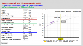
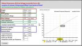
Using the ESL Simulator (Electrostatic Loudspeaker (ESL) Simulator) to calculate dipole ribbon response works quite well.
1) Set D/S Spacing = 1mm, Polarisation Voltage = 1000, Leakage Inductance = 0
2) With those values set, we can calculate a Drive Voltage to represent the magnetic ribbon force.
Vd = 113*B*i/W
Vd = Drive Voltage to represent ribbon force (Vrms)
B = flux density (Tesla)
i = current thru ribbon (Amps rms)
W = width of ribbon (m)
For our test case:
Vd = (113)(0.19)(1)/(19/1000) = 1130 Vrms
3) If desired, an estimated effect of ribbon mass can be included using the Series Resistance Parameter. It isn’t an exact modeling as the radiation impedance assumed is constant. But, it is a reasonable approximation in the high frequency range where the impact to the response is greatest.
Rs = 113*ρal*Dt / (L*W*ρ0*c)
Rs = Series Resistance to represent ribbon mass (ohms)
L = length of ribbon (m)
W = width of ribbon (m)
Dt = thickness of ribbon (μm)
ρ0 = density of air = 1.18 (kg/m^3)
ρal = density of aluminum = 2720 (kg/m^3)
c = speed of sound = 343 (m/s)
For our test case:
Rs = [(113)(2720)(5)] / [(100/1000)(19/1000)(1.18)(343) = 2.0 Mohm
Attachment #1: Screen capture of modeling for the test case excluding ribbon mass.
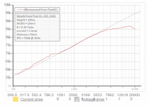
Attachment #2: Screen capture of modeling for the test case including ribbon mass.
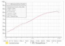
Attachment #3 & #4: Overlays with the measured response .
Attachment #5: Screen capture of modeling if ribbon length was increased to 700mm.
Notice the response starts to flatten out due to differences in arrival time of sound from various areas along the ribbon length(ie it is no long acting like a point source). This results in the SPL at 2kHz being less than the 91.8dB given by the ribbon form of the Walker equation which assumes point source behavior.
Attachments
Last edited:
Thanks very much for all the effort you put into this! It really helps me to better understand the theory behind ribbon drivers.
When the results are so close to the predicted response I must be doing something right
The big challenge now is to keep the distortion down. I already have a new minimal frame ready for further experiments but I haven't yet figured out a better method for clamping the ribbon. Other than minimising distortion the goal is to reduce the height of the frame as much as possible.
regards,
Gerrit
OK. I'm in. I wanna build a couple of these buggers...
Good luck! It takes some doing but it is certainly worth the effort and in the end very rewarding
Gerrit, using tap water or clean water - what difference will it make?
//
Probably very little, it's just my pharmacy background telling me to use demineralised water for chemical reactions (I didn't even think about it).
regards,
Gerrit

Interesting. Brass for some particular reason?
//
No, just because it's readily available, easy to work with and strong enough for this purpose. There's also the possibility of adjusting the width by using different end pieces. The oversized frame allows for different clamping mechanisms to be tested. Ideally I would like to be able to adjust the tension for testing purposes.
regards,
Gerrit
- Home
- Loudspeakers
- Planars & Exotics
- DIY ribbon dipole tweeter, reductio ad minimum