I'm seeking som sort of small adjustment screws so that one could adjust distance between "things" - in this case for instance ribbon tension by adjusting one end. But I haven't spotted something useful yet. It must be small, high precision but still a bit sturdy. I wonder what field of product need this kind of thing..... where/what should one seeks for?
Maybe its just 2 nuts and a screw - M2 or even smaller...
//
Maybe its just 2 nuts and a screw - M2 or even smaller...
//
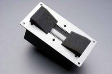
A picture of the brass test frame:
View attachment 526097
Two magnets in stead of three. The idea is to make the ribbon 12cm long so as to move the mounting point out of the gap and provide some flexibility.
regards,
Gerrit
Probably very wise, maybe also attach some damping foam over the two "unused" parts of the ribbon.
Attachments
...maybe also attach some damping foam over the two "unused" parts of the ribbon.
Indeed, I was thinking of using felt. Watching the Raal video on ribbon replacement was what gave me the idea.
regards,
Gerrit
bolserst,
My intention was not to make a highly accurate simulation program.
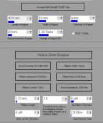
The program was done for showing the implications of changing different variables, using some well known(?) equations.
Its impossible to simulate these things correctly if you think of the number of "small" variables like corrugation type, aluminium type, ribbon tension, dynamically changing gap between magnet and ribbon, baffle design, the effects of the nonlinear magnetic field, and so on into eternity....
But as You can see, the enclosed picture shows 67.4 dB for one ampere at one meter, which gives 73.4 dB at 0.5 meter......
My intention was not to make a highly accurate simulation program.
The program was done for showing the implications of changing different variables, using some well known(?) equations.
Its impossible to simulate these things correctly if you think of the number of "small" variables like corrugation type, aluminium type, ribbon tension, dynamically changing gap between magnet and ribbon, baffle design, the effects of the nonlinear magnetic field, and so on into eternity....
But as You can see, the enclosed picture shows 67.4 dB for one ampere at one meter, which gives 73.4 dB at 0.5 meter......
Attachments
Hi Gerrit
I've made similar ribbon with 2 magnets mounted in U Alu profile.It was 15cm long 13mm wide, with 5 micron foil.
I made Transformer using Amorphouse core AMCC-6. I have also very big Lundahl transformer LL3322 for ribbon. Sound comaparation between transformers didn't show any difference.
Unfortunatelly I already dismounted ribbon without making any photo. Sound is fantastic. For me is much better than Raven 2.0 in my boxes probably because my ribbon was open. I also made another 30 cm long and 25mm wide. This one is even better because can go lower up to1kHz.
Hi Gerrit
I've made similar ribbon with 2 magnets mounted in U Alu profile.It was 15cm long 13mm wide, with 5 micron foil.
I made Transformer using Amorphouse core AMCC-6. I have also very big Lundahl transformer LL3322 for ribbon. Sound comaparation between transformers didn't show any difference.
Unfortunatelly I already dismounted ribbon without making any photo. Sound is fantastic. For me is much better than Raven 2.0 in my boxes probably because my ribbon was open. I also made another 30 cm long and 25mm wide. This one is even better because can go lower up to1kHz.
Longer isn't better, so I'm planning to build something like Your ribbon, 25-30 cm long and 25-30 mm wide.
What magnets did You use, and what about sensitivity?
And maybe I shall buy cores from this Polish site, selling Metglas cores online...
HITACHI cores made form amorphous Metglas materials - DACPOL : SKLEP-PRODUKT
Jonas
never said that longer is better but wider is definitely better according my experience. Of course it can not be too wide because non linearity magnetic field. So far I made 2 sizes 60cm and 15cm. Both with double magnets. In bigger magnets are 30x10x5 and smaller 30x5x10 N52 so same size but magnetization direction different. AMCC cores are best what you can find today. I didn't measure sensitivity just frequency response.
never said that longer is better but wider is definitely better according my experience. Of course it can not be too wide because non linearity magnetic field. So far I made 2 sizes 60cm and 15cm. Both with double magnets. In bigger magnets are 30x10x5 and smaller 30x5x10 N52 so same size but magnetization direction different. AMCC cores are best what you can find today. I didn't measure sensitivity just frequency response.
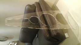
This is plexi frame for my project with 30cm ribbonn. +SEAS excel and Perless 12".
Damned looking slick !
Jonas
never said that longer is better but wider is definitely better according my experience. Of course it can not be too wide because non linearity magnetic field. So far I made 2 sizes 60cm and 15cm. Both with double magnets. In bigger magnets are 30x10x5 and smaller 30x5x10 N52 so same size but magnetization direction different. AMCC cores are best what you can find today. I didn't measure sensitivity just frequency response.
Sorry, I was referring to my own one meter ribbons! When I listen to them, it's almost as big headphones and all vocal music seem to be very near field recordings. Fun in the beginning, but it can get a little tiresome...
This is plexi frame for my project with 30cm ribbonn. +SEAS excel and Perless 12".
Nice, is it done by lasercutting?
Do you happen to know the source for the equations?…The program was done for showing the implications of changing different variables, using some well known(?) equations.
The thread you linked to didn’t seem to provide much information on their origin.
I would be very interested to see their derivation.
I agree…trying to account for every design detail would lead to madness.Its impossible to simulate these things correctly if you think of the number of "small" variables like corrugation type, aluminium type, ribbon tension, dynamically changing gap between magnet and ribbon, baffle design, the effects of the nonlinear magnetic field, and so on into eternity....
I think we are both after the same thing: correct prediction of trends for changes in major ribbon parameters. (field strength, dimensions, mass, current thru ribbon, etc…). Predicting the actual SPL level would be a secondary goal. The ribbon version of the Walker equation seems to provide a better match with measurements without adding any complexity for calculations.
Some trend comparisons for your calculator equation(A) and the Walker equation(B):
Similarities:
1) Field Strength: Both equation A & B give +6dB increase for doubling of average field strength.
2) Current: Both equation A & B give +6dB increase for doubling of current.
3) Ribbon Length: Both equation A & B give +6dB increase for doubling of ribbon length.
4) Ribbon Width: Both equation A & B show no change in output with width if average field strength stays the same.
Differences:
5) Ribbon mass: Equation A gives -6dB loss for doubling of mass, +6dB gain for halving of mass. Equation B gives no change.
In reality, the mass rolls off the response in the top octaves with the majority of the response unchanged. This is because the total moving mass driven by the ribbon is dominated by the airload in all but the top octaves similar to ESLs. In contrast airload is a small portion of the total moving mass of most dynamic drivers, which I believe is the assumption inherent in equation A.
6) Frequency: Equation A has no dependence on frequency. I believe this is because the equation was developed assuming infinite baffle configuration and dimensions smaller than wavelengths of interest. Equation B assumes minimum baffle dipole configuration and gives response increasing +6dB/oct which matches measurements until the mass roll off point is reached.
You would need to reduce Average field strength to 0.19T and ribbon length to 100mm for direct comparison with the Gerrit measurements, giving about 69.6dB @ 50cm. But even so…what frequency would you be comparing with?But as You can see, the enclosed picture shows 67.4 dB for one ampere at one meter, which gives 73.4 dB at 0.5 meter......
I know part of your strategy to address the challenge has been to create magnet configurations that improve the uniformity of the field strength across the gap. I have been meaning to ask, how did you decide on 20mm for the width of your ribbon? When I built my test ribbon from Neo8 magnets I used 3/4"(19mm) gap just because I had some leftover spacers of that dimension already cut out from some ESL experiments.…The big challenge now is to keep the distortion down…
The reason I ask about your chosen gap width is that the JonasKarud ribbon calculator makes it really easy to see that reducing gap width below 20mm can dramatically improve field uniformity. Not having experimented much with ribbons, my original thought was that there would probably be some optimum gap width for best efficiency since increasing gap width reduced field strength but increased radiating area.
However, this may not be the case. According to the ribbon SPL equations, the far-field SPL is proportional to average field strength and Length, but is not a function of width. So if two ribbons have the same length, but one has half the width of the other what would happen? (Assume for a moment that average field strength was the same.) If driven by the same current, the total force on the ribbon is the same, and the far-field SPL would be the same. This would also mean that the half width ribbon would be moving twice as far as the full width ribbon. Now we know that the field strength will be greater for the half width ribbon so it should be louder than the full width ribbon for the same current…likely by 2dB – 3dB.
So, more uniform magnetic field and no loss in sensitivity? What is not to like? Why not keep reducing the gap width and keep gaining improvements? Well, there is the matter of the doubling of ribbon motion for each halving of ribbon width. Also, there will be doubling of heat dissipated in the ribbon for each halving of width. I’m not sure which is would be the more limiting factor…the heat or the increased ribbon motion.
Ok…that was me just thinking while I was typing.
Has anybody tested ribbon of different width but same length driven with the same current?
If not, I may just have to give it a try to compare SPL and distortion for the same drive current.
Can you describe what is better with wider ribbons from your experience?… wider is definitely better according my experience. Of course it cannot be too wide because non linearity magnetic field.
Thanks
")
I know part of your strategy to address the challenge has been to create magnet configurations that improve the uniformity of the field strength across the gap. I have been meaning to ask, how did you decide on 20mm for the width of your ribbon? When I built my test ribbon from Neo8 magnets I used 3/4"(19mm) gap just because I had some leftover spacers of that dimension already cut out from some ESL experiments.
The reason I ask about your chosen gap width is that the JonasKarud ribbon calculator makes it really easy to see that reducing gap width below 20mm can dramatically improve field uniformity. Not having experimented much with ribbons, my original thought was that there would probably be some optimum gap width for best efficiency since increasing gap width reduced field strength but increased radiating area.
However, this may not be the case. According to the ribbon SPL equations, the far-field SPL is proportional to average field strength and Length, but is not a function of width. So if two ribbons have the same length, but one has half the width of the other what would happen? (Assume for a moment that average field strength was the same.) If driven by the same current, the total force on the ribbon is the same, and the far-field SPL would be the same. This would also mean that the half width ribbon would be moving twice as far as the full width ribbon. Now we know that the field strength will be greater for the half width ribbon so it should be louder than the full width ribbon for the same current…likely by 2dB – 3dB.
So, more uniform magnetic field and no loss in sensitivity? What is not to like? Why not keep reducing the gap width and keep gaining improvements? Well, there is the matter of the doubling of ribbon motion for each halving of ribbon width. Also, there will be doubling of heat dissipated in the ribbon for each halving of width. I’m not sure which is would be the more limiting factor…the heat or the increased ribbon motion.
Ok…that was me just thinking while I was typing.
Has anybody tested ribbon of different width but same length driven with the same current?
If not, I may just have to give it a try to compare SPL and distortion for the same drive current.
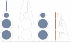
Here's a width comparison for a 40cm long ribbon, 15mm gap. Ribbon width 10mm (red), 11mm (green), 12mm (orange), 13mm (blue), 14mm (black):

For the recent designs I choose a 20mm gap to keep the excursion small because the field is not linear. I simulated a lot of designs in FEMM and found a 20mm gap to be the best compromise between field uniformity and radiating surface.
regards,
Gerrit
No, I do not know the source for the equations.
But I'll be doing some research.
I'm just a messenger who transformed the simple equations into a simple Delphi program, don't shoot me.
One thing is good with the program though, it made it easy to spot faults in the equations! (if there are any).
If anyone has better ribbon simulation equations, let me know so that we can improve the program together.
Ribbon temperature would be a nice thing to know at different current flows...
Last edited:
I've been googling "Simple ribbon equations" and found that the origin probably is in "Justus V.Verhagen: Ribbon Loudspeakers, side 8.
Ribbon Loudspeakers by J.V.Verhagen - code 5007 | Hifi Collective
I'm not sure about this, but it's a possible candidate! You decide!
Ribbon Loudspeakers by J.V.Verhagen - code 5007 | Hifi Collective
I'm not sure about this, but it's a possible candidate! You decide!
- Home
- Loudspeakers
- Planars & Exotics
- DIY ribbon dipole tweeter, reductio ad minimum