That is exactly what I was thinking...that perhaps the airload on the minimal ribbon is more uniform compared to the ribbon with hourglass baffle. With relative airload on the center portion of the ribbon being less than on the ends, it might be more prone to resonance.
Interesting….that was my other thought that differences in flux distribution might make the ribbon more/less prone to resonance. It might also just be that with 2x the flux density, the force on the ribbon exceeds some thresholds and breaks into resonance.
Have you thought about experimented with adding a layer of tightly stretched acoustic mesh to the back of the ribbon opening to try to acoustically damp the resonance? This works well for ESLs.
The reduced air load in the center could certainly have an effect. This will be something I'll look out for when I try the cardboard baffle. Another experiment would be to straighten the hourglass and see if that affects the resonance.
I thought about using a damping mesh after reading your remarks on the modified Neo8. I have some nice stretch speaker cloth I could try, it would also protect the ribbon from draft.
Trying a different suspension could also be worthwhile.
Lots of things to do in the coming winter months.
")
regards,
Gerrit
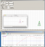
Made some efforts in Edge to see how the shape of a baffle interact with a ribbon. Whit such a light transducer I also wonder how a different impedance effects the membrane. Where the baffle is wider it will see a greater load than where its narrower. Does this create an imbalance that causes distorsion? I found the triangle to give the most smooth response if one want vertical symmetry which I think I do.
Attachments
Made some efforts in Edge to see how the shape of a baffle interact with a ribbon. Whit such a light transducer I also wonder how a different impedance effects the membrane. Where the baffle is wider it will see a greater load than where its narrower. Does this create an imbalance that causes distorsion? I found the triangle to give the most smooth response if one want vertical symmetry which I think I do.
What about the directivity? I don't see how this is an advantage over the minimal ribbon. A steel triangle will also lead to an uneven flux in the gap because of the difference in magnetic return path.
It is not my intention to further improve the steel frame, I will concentrate on the minimal ribbon. The minimal ribbon has a bulge in the directivity at 10kHz, the steel frame ribbon has a bigger bulge at 7kHz. The lower the frequency the more it will affect the stereo imaging, so I'd rather have it as high as possible.
regards,
Gerrit
OK! The triangular baffle need not to be made of steel. The directivity bulge is a concern. Maybe a very small and thin triangle. But I will build a minimal and test with different extra appendixes.
//
What do you want to achieve with the baffle? Do you want to avoid the dipole loss?
regards,
Gerrit
Yes, some sustain in the lower region + get away from symmetrical distances. This is to spread out the resonances. It's a trade against directivity.
When cutting sails, the sailmaker always makes an undercut (concave) side as otherwise it will flap in the wind. This might be something to consider when forming a ribbon... it shall maybe be a tiiiiny wee smaller in the waist? I will try this.
Also the terminating sides should not be parallell. I will try this.
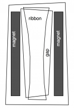
Maybe even the long sides in the gap should not be physically parallel (magnets should most probably!). I will try this.
I belive removing parallell symmetries could pay off in a less resonant system. Maybe the sum of resonances are equal but the none parallell system will have less distinct ones.
//
When cutting sails, the sailmaker always makes an undercut (concave) side as otherwise it will flap in the wind. This might be something to consider when forming a ribbon... it shall maybe be a tiiiiny wee smaller in the waist? I will try this.
Also the terminating sides should not be parallell. I will try this.
Maybe even the long sides in the gap should not be physically parallel (magnets should most probably!). I will try this.
I belive removing parallell symmetries could pay off in a less resonant system. Maybe the sum of resonances are equal but the none parallell system will have less distinct ones.
//
Attachments
Last edited:
i think gerrit has different goals. look like lowest thd and a true dipole behavior. witch you cant get with a triangle.
that said you wont get it with the minimal ribbon either. i mean there will be a baffle either way be it the magnets or a super structure of metal from the motor.
you can spread the problems the baffle gives you but then the field wont be nice, so its a balance of thd (and efficiency) and baffle
still a baffles motor gives the best result (for the true dipole quest)as Gerrit proved so far. , also i must say the stuff you made looks awesome !!!! you got a cnc or laser cutter (that can mill steel) yourself or you order these pieces of metal ? looks expensive. and beautiful!
p.s ill take a look at the binaural recordings tomorrow i forgot all about them
Last edited:
Yes, some sustain in the lower region + get away from symmetrical distances. This is to spread out the resonances. It's a trade against directivity.
When cutting sails, the sailmaker always makes an undercut (concave) side as otherwise it will flap in the wind. This might be something to consider when forming a ribbon... it shall maybe be a tiiiiny wee smaller in the waist? I will try this.
Also the terminating sides should not be parallell. I will try this.
Maybe even the long sides in the gap should not be physically parallel (magnets should most probably!). I will try this.
I belive removing parallell symmetries could pay off in a less resonant system. Maybe the sum of resonances are equal but the none parallell system will have less distinct ones.
//
It could prove very difficult to cut the ribbon in such a shape and I don't see how this would help without introducing other problems. Looking at the way Raal does it I was thinking of making the ribbon longer so that about 1cm on each side will not radiate sound and will act as a 'suspension'.
... also i must say the stuff you made looks awesome !!!! you got a cnc or laser cutter (that can mill steel) yourself or you order these pieces of metal ? looks expensive. and beautiful!
Thank you
The steel frames were made by someone else as I don't have the machinery to do that. I traded them for some tube amp parts I no longer used. All other parts and stuff I did myself.
The little plastic parts I did with my table saw:

It's a matter of clamping the material, using the right blade and pulling the saw through the material so your fingers are nowhere near the saw.
regards,
Gerrit
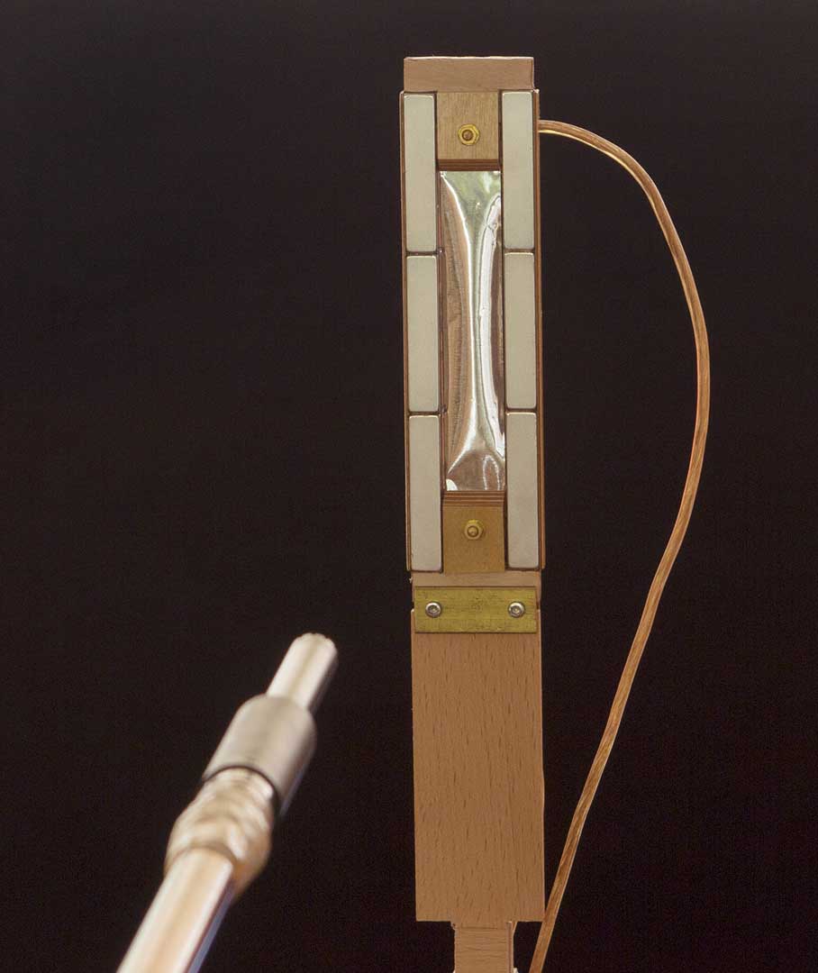
I think this picture is really interesting. Now, if we should substitute the ribbon by say 10pc of 2mm ribbons close side by side we would see an opposite view where the ribbons on the sides would make the greatest excursion (twice that of the center due to double flux?) rather than what can be seem here. Is there sometime to be gained by a different suspension...? How can it behave like this - one would think that the ribbon is tensioned equally hard but still the centre can bulge. What is giving away?
//
//
Last edited:
I used to make the strips wider where the field was stronger:I think this picture is really interesting. Now, if we should substitute the ribbon by say 10pc of 2mm ribbons close side by side we would see an opposite view where the ribbons on the sides would make the greatest excursion (twice that of the center due to double flux?) rather than what can be seem here.

How can it behave like this - one would think that the ribbon is tensioned equally hard but still the centre can bulge. What is giving away?
Perhaps:
- The ribbon used is not rigid enough, corrugate it?
- Resonance.
- The ribbon is so tightly mounted that only the middle can move, being some distance from the suspension.
I think this picture is really interesting. Now, if we should substitute the ribbon by say 10pc of 2mm ribbons close side by side we would see an opposite view where the ribbons on the sides would make the greatest excursion (twice that of the center due to double flux?) rather than what can be seem here. Is there sometime to be gained by a different suspension...? How can it behave like this - one would think that the ribbon is tensioned equally hard but still the centre can bulge. What is giving away?
//
HMm i was thinking is the sides not where the biggest flux is ? hence this is not a forward motion but a backward and the middle is lagging behind ? hence the bulge?
or could you see if the wave responsible was positive ? keeping in mind all is connected correctly in phase of course. i mean the edged are near the magnets almost touching it.
Yeah, we must know what the applied signal looks like.HMm i was thinking is the sides not where the biggest flux is ? hence this is not a forward motion but a backward and the middle is lagging behind ? hence the bulge?
or could you see if the wave responsible was positive ? keeping in mind all is connected correctly in phase of course. i mean the edged are near the magnets almost touching it.
Also, it could be good to see this from the side or from above.
Just a quick couriosty!
For the fun of it, I made a one meter membrane of 40 uM (almost cat and toddler proof!) clear packing tape and 10 uM alu.
It's almost impossible to corrugate, but it has a very,very and very nice sound to it!
(Yes, I have excellent hearing according to resent audiologics tests, and if You don't believe me You're all invited for a cup of coffee and some cakes to hear for Yourself!)
Last edited:
You´re probably right.Ok knowing the flux I should really have interpreted the picture as the center being "still" and the sides moving. Duh!
Do you have a link to where you found the picture?
Sorry, I have actually been following the thread from the start and you´re right, the picture is from one of the first posts.Solhaga it's from this thread. And we do know about corrugation. You probably need to read the threat to discuss properly in context ;-)
//
The thread is really interesting and has a very high level of technical discussions.
Again, sorry for my ignorance. I guess I didn't pay enough attention.
Actually, I've been thinking of building a synchronized and stroboscopic thingumajig.Well what i mentioned was just a option, Gerrit could shine a light on the picture, he took it
nowadays with iphones i think they can even record slowmotion. if frequency signal not chosen to high it should be visible
Problem is to get it in sync with the audio signal applied.
But just any modern camera or video camera will probably do as the recorder as you suggests Wrinex.
The video camera I have have (Sanyo HD2000) is capable of 600 fps. So you should be able to look at a 150 Hz input signal with 4 frames per cycle.
If you are patient though, you should be able to for example catch the ribbon at its excursion limit.
And perhaps that is what Gerrit did.
Last edited:
The picture was taken with a high level sine wave signal of about 1-2kHz. I took this picture to show what happens if there is no corrugation or any other method of stiffening. The field is not constant across the gap and this will cause the ribbon to flex, the center lags behind the edges. With a sine wave sweep you can actually see it happening if the frequency is low and the level high. The minimal ribbon frame has no way to really tension the ribbon, hence the testframe that I'm working on which allows me to tension the ribbon in a more controlled fashion.
regards,
Gerrit
regards,
Gerrit
- Home
- Loudspeakers
- Planars & Exotics
- DIY ribbon dipole tweeter, reductio ad minimum