How would one go about to determine which of the two situations that has actually arisen?
I'm perfectly with you on the system perspective. I think on system level there is a lot of synergistic effects playing the end result. Personally I'm not prepared to play that card (fine tuning) until I have done every measure possible to acquire individual high performance system components. But one needs a system architectural idea to base the build on. I maintain 2 paths at the moment - wall integrated or bipol (OB) with a little bias on the latter. See where it ends up.
//
How would one go about to determine which of the two situations that has actually arisen?
I'm perfectly with you on the system perspective. I think on system level there is a lot of synergistic effects playing the end result. Personally I'm not prepared to play that card (fine tuning) until I have done every measure possible to acquire individual high performance system components. But one needs a system architectural idea to base the build on. I maintain 2 paths at the moment - wall integrated or bipol (OB) with a little bias on the latter. See where it ends up.
//
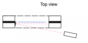
I thought of using a laser and let the beam reflect of the ribbon. One of those lasers they use for projecting a line on a wall should work.
Btw - Gerrit, are you using the taro or resistors in these measurements?
The higher drive impedance of the resistor could have positive effects?
//
For these measurements I used the NCore400 with a 2Ω series resistor made of four 0.5Ω 100W Caddock non-inductive film resistors.
On a Dutch forum there have been reports and measurements that show that a higher drive impedance results in lower distortion with tweeters. My own measurements also point in that direction.
regards,
Gerrit
I thought of using a laser and let the beam reflect of the ribbon. One of those lasers they use for projecting a line on a wall should work.
Cool!
So if the laser i set to a certain excursion you would start to see it shine red if they meet - kind of a overload indicator. If not it would just be a red dot on the side wall. How do you get the laser within the frame?
//
Attachments
Cool!
So if the laser i set to a certain excursion you would start to see it shine red if they meet - kind of a overload indicator. If not it would just be a red dot on the side wall. How do you get the laser within the frame?
//
My idea was to let the beam reflect of the middle of the ribbon onto the wall or a screen, but it's just an idea to somehow make use of the fact that the ribbon has a reflective surface.
regards,
Gerrit
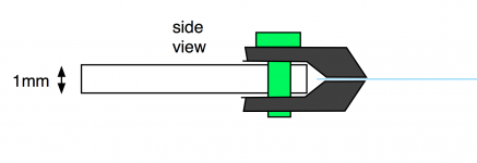
Re: suspending the ribbon... does your clamps locate the ribbon dead center of the 1mm layer between the magnets? Hard to tell form the pictures and maybe not trivial to achive?
Yes, the ribbon is exactly is the middle. This is indeed a critical step and I took great care to postion the contact blocks. Using a sheet of glass to provide a flat and smooth surface and a big illuminated magnifying glass I think I got it accurate to about 0.05mm.
regards,
Gerrit
OK.. I should have thought so ")
And how about tensioning the ribbon... Raal uses "shrink wrap" and heat...
https://www.youtube.com/watch?v=bvylZF9eJOA
//
And how about tensioning the ribbon... Raal uses "shrink wrap" and heat...
https://www.youtube.com/watch?v=bvylZF9eJOA
//
Possibly in order to get the resonances/distorsion down in the lower frequencies, you need to tension the ribbon. Now, due to the quite heavy corrugation, the ribbon is a spring and it won't help much to pull it in one end. Probably in order to get an improvement in the low end department, the ribbon needs to be flatter so that it can be set under higher tension. Raal has some seemingly very shallow corrugation. But I understand you tried a thinner wire flat-cable!?
//
//
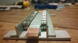
A while back I macgyvered this setup to measure the Bl product:
Did you ever use this setup to measure the average flux density in your ribbon with the hourglass shaped magnetic return path?
Oh, and speaking of the hourglass shape, I have been meaning to ask about the resonance peaks you have been fighting with. Did you have as big a problem with resonances with your minimal ribbon structure? Or does it seem to be more difficult to eliminate with the hourglass shaped return path.
OK.. I should have thought so
And how about tensioning the ribbon... Raal uses "shrink wrap" and heat...
https://www.youtube.com/watch?v=bvylZF9eJOA
//
Interesting approach, thanks for the link.
As for your other remarks. It seems like a good idea to build a test frame to investigate different mounting schemes for the ribbon.
Did you ever use this setup to measure the average flux density in your ribbon with the hourglass shaped magnetic return path?
Oh, and speaking of the hourglass shape, I have been meaning to ask about the resonance peaks you have been fighting with. Did you have as big a problem with resonances with your minimal ribbon structure? Or does it seem to be more difficult to eliminate with the hourglass shaped return path.
No, the frame is the heavy for the scale. I would need to change the setup.
Good question. The resonance is definitely an issue with the minimal ribbon. I could use a 'cardboard cutout' to give the minimal ribbon the same shape as the steel frame, this would allow for a better comparison.
Contrary to what one would expect the flux in the minimal frame is strongest at the top and bottom of the gap.
regards,
Gerrit
... I could use a 'cardboard cutout' to give the minimal ribbon the same shape as the steel frame, this would allow for a better comparison.
This would be interesting to see.
... Contrary to what one would expect the flux in the minimal frame is strongest at the top and bottom of the gap.
Would a say 1 x 10mm steel frame change this significantly? Like a very thin frame.
Is this the reason why you only utilize 10 out of 15cm flux gap?
//
This would be interesting to see.
Would a say 1 x 10mm steel frame change this significantly? Like a very thin frame.
Is this the reason why you only utilize 10 out of 15cm flux gap?
//
Yes, based on simulations in FEMM I decided to use 10cm out of 15cm. The goal was to get a constant flux in the part where the ribbon is placed. As the ribbon moves the easiest in the middle it may not be necessary to have a constant flux, it could even prove to be counter productive.
For the test frame I want to use 2 magnets for a 10cm gap. I want to minimise the hight in order to decrease the center to center distance to whatever driver is above or below it.
regards,
Gerrit
Okey so I could not wait for my magnets so I went along and did a zero prototype just to get a feeling what I'm up to. Was a good excerise. Did al the errors. Got a metal file to crash the magnet structure - just to start again (used quick glue) Realized that soldering the terminations is not so easy as the one might loose the other side due to copper heat conductivity. But it plays. Not very load - use a 2,6 ohm resistor. I don't have a crossover so I produced a number of files HP:ed at 3K. Its not very load but I think I can hear "it" ....
I recalled chocolate to have thin inner sleeving of aluminum foil. Used that. Had some nice side effects also
//
Realized that soldering the terminations is not so easy as the one might loose the other side due to copper heat conductivity. But it plays. Not very load - use a 2,6 ohm resistor. I don't have a crossover so I produced a number of files HP:ed at 3K. Its not very load but I think I can hear "it" ....I recalled chocolate to have thin inner sleeving of aluminum foil. Used that. Had some nice side effects also
//
Attachments
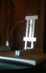

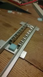
Okey so I could not wait for my magnets so I went along and did a zero prototype just to get a feeling what I'm up to. Was a good excerise. Did al the errors. Got a metal file to crash the magnet structure - just to start again (used quick glue)
I recalled chocolate to have thin inner sleeving of aluminum foil. Used that. Had some nice side effects also
//
And so it begins...
regards,
Gerrit
Other options
Hi
So far i have only read half of the thread.
I will read the rest later, but i have some ideas that i want to post before I forget them. So please forgive me if it is too stupid
Two thing i have been thinking off.
1. Is it possible to use electro magnets?
2. I have seen that some aluminium domes have been eloxated so they get hard as ceramic, can that be usefull? That should make the aluminium foil stiff.
best regards
Uwe
Hi Uwe,Hi
So far i have only read half of the thread.
I will read the rest later, but i have some ideas that i want to post before I forget them. So please forgive me if it is too stupid
Two thing i have been thinking off.
1. Is it possible to use electro magnets?
2. I have seen that some aluminium domes have been eloxated so they get hard as ceramic, can that be usefull? That should make the aluminium foil stiff.
best regards
Uwe
Electromagnets would be impractical. Neodymium magnets have the best strength to size ratio. Electromagnets would become very bulky.
(electro) chemical treatment could be an option but I would like to keep it simple.
I'm going to build a special minimal frame for testing. Looking at the Raal instruction video got me thinking about trying a high tension ribbon with a minimal embossed pattern, maybe with some damping at the ends.
In the meantime I've mounted the steel frame drivers on their base:

Essentially a Linkwitz Pluto clone. The crossover is at 1500Hz 24dB/oct LR.
The response for several angles:

The steel frame acting as a baffle is responsible for the peak off-axis around 7kHz.
At the crossover between omnipole and dipole the system becomes a cardioid. At 180 degrees the dipole is out of phase and the resulting null creates the cardioid pattern. This can be seen in the (normalised) polar diagram:

The null is not sharp enough yet as I'm still tuning the filter. The full 360 degree directivity diagram:

Ideally the narrow white areas should continue and follow the green areas around the corner so to speak.
Alas, the plate amps broke down for reasons unknown to me so I haven't been able to listen to the system. They're on their way to Hypex and I expect them to be back soon.
regards,
Gerrit
That is exactly what I was thinking...that perhaps the airload on the minimal ribbon is more uniform compared to the ribbon with hourglass baffle. With relative airload on the center portion of the ribbon being less than on the ends, it might be more prone to resonance.Good question. The resonance is definitely an issue with the minimal ribbon. I could use a 'cardboard cutout' to give the minimal ribbon the same shape as the steel frame, this would allow for a better comparison.
Interesting….that was my other thought that differences in flux distribution might make the ribbon more/less prone to resonance. It might also just be that with 2x the flux density, the force on the ribbon exceeds some thresholds and breaks into resonance.Contrary to what one would expect the flux in the minimal frame is strongest at the top and bottom of the gap.
Have you thought about experimented with adding a layer of tightly stretched acoustic mesh to the back of the ribbon opening to try to acoustically damp the resonance? This works well for ESLs.
- Home
- Loudspeakers
- Planars & Exotics
- DIY ribbon dipole tweeter, reductio ad minimum