


Hi Ian,
thanks for your comments. This is the reason why I posted it here. I'm only a mechanical engineer ....
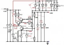
But if this is the onliest serious problem I think I found the solution. In the orginal schematics there is a "+80V REGULATED" and a "+80V UNREGULATED" power input. I think my interpretation that UNREGULATED is "0V" was simply wrong.

Se my comments in the right top corner:
If there is no "+80V REGULATED" input, "+80V REGULATED" and "+80V UNREGULATED" must be the same. Is this right?
This will bring me to another improvement opportunity for the new PSU which is still not printed. What is neccessary to implement a "Regulated 80V" supply on the PSU Board?
Another question I have is related to the hand written sketch on the left side: In the schematics the connection of VR1 Pisher is not correctly done. I already corrected it. But is the direction the right one?
What other serious problems are in my transfered schematics?
Regards from a mechanical engineer
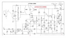
Here's circuit diagram for battery sound output for your amplifier
The labelling is still wrong, but the schematic is more or less correct, as far as I can see. There is no -80V because the amp only uses +80V, here split between two separate lines for a possible regulated supply for the input and VAS stage. The two 0V/grounds sides are seperated and connect to a single point not shown on the drawing.
Do you find any other faults?
See
Attachments
Hi Ian,
thanks for your comments. This is the reason why I posted it here. I'm only a mechanical engineer ....
But if this is the onliest serious problem I think I found the solution. In the orginal schematics there is a "+80V REGULATED" and a "+80V UNREGULATED" power input. I think my interpretation that UNREGULATED is "0V" was simply wrong.
Se my comments in the right top corner:
If there is no "+80V REGULATED" input, "+80V REGULATED" and "+80V UNREGULATED" must be the same. Is this right?
This will bring me to another improvement opportunity for the new PSU which is still not printed. What is neccessary to implement a "Regulated 80V" supply on the PSU Board?
Another question I have is related to the hand written sketch on the left side: In the schematics the connection of VR1 Pisher is not correctly done. I already corrected it. But is the direction the right one?
What other serious problems are in my transfered schematics?
Regards from a mechanical engineer
Your circuit diagram is not correct. see
Attachments
Your circuit diagram is not correct. see
I think, we already discussed it. But I'll doublecheck before I'll send the PCB's to production ....
Thanks
Ingo
.... the new PSU PCB is completed

See also here: http://www.diyaudio.com/forums/power-supplies/216460-regulated-80v-supply-8.html
See also here: http://www.diyaudio.com/forums/power-supplies/216460-regulated-80v-supply-8.html


Short update:
CPA 602 - S/N: 11111 ... Sucsessfull update ....New PSU works ...
CPA 602 - S/N: 10943 ... Update failed .... Power Amp boards burned .... both. This is the one which was recapped and the circuits were changed. No chance so far to get it back to life ....
Stepped back one step, good to have the passive crossovers for the ARC050 ....
First listening impression with working 11.111: I can see more details on the stage ... even with the passive crossover.
Now I need to speed up the new PCB's for the first NERO .... Will be also a repair kit for burned CPA 602's .... 11.111 works perfect together with the new PSU ....
I'll post some pics tomorrow ....
As promised, some pics from yesterday evening:
New and old PSU PCB's ...

New PSU PCB and new Toroid in good old CPA 602 ....


This one burned ...

S/N 10943
On boath amp boards R17 looked like coal ...... There is an issue with the common ground of both rails ....
R17 were replaced and we see light at the tunnel that we bring Burnie2 back to life soon ......
New and old PSU PCB's ...
New PSU PCB and new Toroid in good old CPA 602 ....
This one burned ...
S/N 10943
On boath amp boards R17 looked like coal ...... There is an issue with the common ground of both rails ....
R17 were replaced and we see light at the tunnel that we bring Burnie2 back to life soon ......
Short update .... 
NERO Box Prototypes arrived ..... need some fine adjustments, but result can bee easily seen ....
That's for the CAP602-Clone ......


So, please give me your comments ..... and I know, the painting can be improved. And it will be ......
And if the fine adjustments are done, I'll provide better pictures .... promised
NERO Box Prototypes arrived ..... need some fine adjustments, but result can bee easily seen ....
That's for the CAP602-Clone ......
So, please give me your comments ..... and I know, the painting can be improved. And it will be ......
And if the fine adjustments are done, I'll provide better pictures .... promised
Last edited:
I had a problem with the toroids. Got very warm ..... But Problem solved, the screws which fixed the toroid in the housing was to long. Touched the bottom and the top of the housing. Must be a very stressy magnetic field. Since I've shortend the screw it get better.
Normal temperature as before the change to the new toroids.
After listening now for several hours I can say that this step was a big improvement for the good old Nytech CPA 602's ....
I can summarize that there is now a wonderful3D stage in my listening room. This was even better in the passiv mode without the electronic crossover. The electronic crossover follows this improvement for 50%.
This will now be the next step to improve.
Gentlemen, any suggestions from you how to improve the electronic crossover from the CXA252?

The ideas so far are:
- Setup also a dual rail power supply for the XO
- Use Vishay Dale CMF55 0.1% antimagnetic resistors
- Use WIMA 1% Film Caps instead of the ceramic ones ...
- and what Else?
Maybe there are some opportunities to improve also the circuits....
Regards from Germany
Ingo
Normal temperature as before the change to the new toroids.
After listening now for several hours I can say that this step was a big improvement for the good old Nytech CPA 602's ....
I can summarize that there is now a wonderful3D stage in my listening room. This was even better in the passiv mode without the electronic crossover. The electronic crossover follows this improvement for 50%.
This will now be the next step to improve.
Gentlemen, any suggestions from you how to improve the electronic crossover from the CXA252?
The ideas so far are:
- Setup also a dual rail power supply for the XO
- Use Vishay Dale CMF55 0.1% antimagnetic resistors
- Use WIMA 1% Film Caps instead of the ceramic ones ...
- and what Else?
Maybe there are some opportunities to improve also the circuits....
Regards from Germany
Ingo
Short update: September 24th 2012
Toroids for my 602s Clone arrived from Poland ...

The two small ones are for the 602s in Dual Mono Design ... the big one is for the HiCap Clone.
The two small ones fit perfectly into my new housing.

I'll keep you updated ....
Regards from Germany
Ingo
Toroids for my 602s Clone arrived from Poland ...
The two small ones are for the 602s in Dual Mono Design ... the big one is for the HiCap Clone.
The two small ones fit perfectly into my new housing.
I'll keep you updated ....
Regards from Germany
Ingo


- Status
- This old topic is closed. If you want to reopen this topic, contact a moderator using the "Report Post" button.
- Home
- Amplifiers
- Solid State
- DIY Project - Nytech CPA602 today ...