"There were a multitude of other clever design tricks in the Nytechs and Ions. ... There are other real improvements that can be made to the already well designed Nytech/Ion power/pre amp circuits that do nothing but develop its qualities further. ... What I hope to do one day is design an amp that incorporates all the best bits of the Nytech and Ion amps, and have it all on a single circuit board in a decent case. That would be a winner."[/I]
Very, very good, but it is so easy to say. How often have I heared that or similar sentences but this and that amp. But very little practical knowledge followed... some ideas maybe are not so easy to implement from paper work or simulations.
Some modifications I know of are:
Better regulation for the input stage, because it is a very sensitive spot.
Parts selection, because ceramics and cheap elcaps are not the best choice perhaps. But that is as obvious as difficult, because it can alter the way the amp will behave beeing pushed to the limits.
Instead of adding things like current mirrors and the like, leaving things out like the current limiter and the anti-thump circuits. This is a typical non-commercial modification: "...sounds good, so do it if you dare to but do not make us responsible if anything unwanted will happen..."
These are some examples I have already tried with good results re-creating an Obelisk2 (without the first one actually).
Another possibilty could be a new pcb with very strict star grounding - a bit like the old and very good Creek4040 where the power star ground and the signal star ground are joined not even on the pcb but right at the psu capacitor itself.
There are definitely better transistors than the ones you have mentioned. But I must admit that I do not have much experience with those. I selected the input transistors - the most critical part in my opinion - to similar with relatively high hfe. The VAS transistor similar, this could probably be a better/stronger transistor but must be fast and have high gain - there are only two stage for gain in that amp. The "legendary" BlackDevil Amplifier from the long gone german magazine "elrad" used an UHF transistor in the stage. That was an even simpler amplifier than the Nytechs/Ions (using just four transistors) with a phantastic sound quality. I will send you some texts about that in pm.
Maybe I should make a nnew piar of those again - the first one is long gone.
Maybe I should make a nnew piar of those again - the first one is long gone.
Last edited:
Ok so far .....
Better Regulation for the input stage is actually discussed here: http://www.diyaudio.com/forums/power-supplies/216460-regulated-80v-supply.html looks very promising for me.
Parts selection:
For the cap's my choice will be:

For the small 10uF I found bipolar Elnas on Ebay.
New PCB with Star Grounding???? sounds good ....
What is neccessary to do .....
Better Regulation for the input stage is actually discussed here: http://www.diyaudio.com/forums/power-supplies/216460-regulated-80v-supply.html looks very promising for me.
Parts selection:
For the cap's my choice will be:
For the small 10uF I found bipolar Elnas on Ebay.
New PCB with Star Grounding????
sounds good ....What is neccessary to do .....
Maybe I should make a nnew piar of those again - the first one is long gone.
Sounds like another project for new housings .....
Very, very good, but it is so easy to say. How often have I heared that or similar sentences but this and that amp. But very little practical knowledge followed... some ideas maybe are not so easy to implement from paper work or simulations.
Some modifications I know of are:
Better regulation for the input stage, because it is a very sensitive spot.
Parts selection, because ceramics and cheap elcaps are not the best choice perhaps. But that is as obvious as difficult, because it can alter the way the amp will behave beeing pushed to the limits.
Instead of adding things like current mirrors and the like, leaving things out like the current limiter and the anti-thump circuits. This is a typical non-commercial modification: "...sounds good, so do it if you dare to but do not make us responsible if anything unwanted will happen..."
These are some examples I have already tried with good results re-creating an Obelisk2 (without the first one actually).
Another possibilty could be a new pcb with very strict star grounding - a bit like the old and very good Creek4040 where the power star ground and the signal star ground are joined not even on the pcb but right at the psu capacitor itself.
I'm really interested what the author has/had in his mind ... seems to be a real specialist. He's also a user in this forum. One of my 602's was recapped by him. Sounds really good ... and there are big changes in the circuits of the recapped 602. C3 was replaced by a ceramic cap. Then red Elnas were used ... don't remember the brand names.
Last edited:
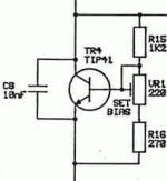
For the new CPA602 I suggest to use the tracking schematics Ion used for ll their later amps (the one with the TIP41). This transistor should be mounted right between the power transistors.
As the CPA602 is not using darlington transistors this may not be so necessary here - I would do it nevertheless.
As the CPA602 is not using darlington transistors this may not be so necessary here - I would do it nevertheless.
This forum or that in pinkfish? What big changes you mean?
He wrote it on Pinkfish. He made changes in the circuits of my 602. I've found it on ebay. He changed between elcos and ceramic caps and changed also the values ....
For the new CPA602 I suggest to use the tracking schematics Ion used for ll their later amps (the one with the TIP41). This transistor should be mounted right between the power transistors.
As the CPA602 is not using darlington transistors this may not be so necessary here - I would do it nevertheless.
Is the TIP41 a replacement for TR3?
Is it in the Ion3 or Nexus? I have to look into the schematics ...
He wrote it on Pinkfish. He made changes in the circuits of my 602. I've found it on ebay. He changed between elcos and ceramic caps and changed also the values ....
Well, I would not call that big changes. Do you have a list of all the modifications?
Is the TIP41 a replacement for TR3?
Is it in the Ion3 or Nexus? I have to look into the schematics ...
Yes. The tracking schematic is the same for all ION amps.
Attachments
For the new CPA602 I suggest to use the tracking schematics Ion used for ll their later amps (the one with the TIP41). This transistor should be mounted right between the power transistors.
I think, can also be implemented in the original ones ..... Maybe with it's own heatsink.
Well, I would not call that big changes. Do you have a list of all the modifications?
Yes, somewhere I have a list and I have pics with the caps ....
Will look for the list ...... or will prepare a new one.


The Layout for the new CPA 602s PCB is finished:


It's more or less the same Layout as in the original 602's.
To replace TR3 as used in the ION/NEXUS the Layout will be changed a little bit, and the TR3 will be moved to the heatsink.
Comments and improvement suggestions are warmly welcome ....
Can somebody give me a tip how to mirror the board with Eagle?
- Status
- This old topic is closed. If you want to reopen this topic, contact a moderator using the "Report Post" button.
- Home
- Amplifiers
- Solid State
- DIY Project - Nytech CPA602 today ...