RHosch said:Vacuum forming will reduce weight, if that is a goal, but it isn't absolutely necessary to make a strong laminate. If you don't use vacuum assist then the final laminate will be thicker for a given strength, but it will also be a bit stiffer for a given strength. If weight isn't a concern, then hand layup with a well wetted cloth would be just fine. The extra resin will only affect weight and stength... not stiffness, which is the primary characteristic that is desired in the sandwich skins.
This is important that everybody understands is dead wrong. Very important !!!
The higher epoxy percentage a given fibre ithem has, the softer it becomes. The structural strength of epoxy is very low, its just there to hold the fibres in position. If you make it without vaccuum, you get a heavier and softer result.
The balse solution is theoretically good, but hard to implement in a cone. The balsa end wood will be extreemely fragile and hard to handle in a lets say 3 to 5 mm thickness. I know the principial behind it, its among other places used for wings for wind turbines and yachts.....its hard to use in smaller scale.
I would use 2 layers of 60 grams per sq meter carbon. 50-50 bi-directional, Angled 45 degrees the layers in between. For each side of the sandwich that is.
The cone must btw be shaped, it cant be flat. Preferably psferic....it would make it stronger...much stronger.
As for the price of carbon here, its around 170 usd per kilogram.....keep in mind that you need no more than 100 grams
")
Pretty much any slow curing epoxy will do for this, 24hrs or more.
Magura
As my graduate research was primarily dealing with composite structures, and my current career is designing and analyzing composite structures for classified military applications, I am somewhat familiar with these materials and how they can be used.Magura said:This is important that everybody understands is dead wrong. Very important !!!
Yes, and this is just what I said above. Surface hardness (which you describe using "softer") is related to strength, not stiffness. In this application, my educated guess is that stiffness considerations in the sandwich skins will dominate. As such, the strength/weight ratio isn't all that important, just the final stiffness. Neglecting vacuum forming won't impact stiffness much at all... only the strength/weight ratio. So long as the same volume of carbon is used, both hand layup and vacuum assist methods will produce a laminate of roughly equivalent stiffnesses, but with quite different strengths (and weights).The higher epoxy percentage a given fibre ithem has, the softer it becomes. The structural strength of epoxy is very low, its just there to hold the fibres in position. If you make it without vaccuum, you get a heavier and softer result.
Additionally, I doubt that the weight of the diaphram will need to be kept low. With such a strong motor, you probably want a fairly high mass diaphram, which further reduces the importance of the laminate weight. And, it also reduces the importance of a cone shaped diaphram. A flat diaphram can be made just as rigid as a cone shaped one, at a cost of higher weight. If you need higher weight anyway, it is a perfect fit. Someone like Bill Fagal will have to contribute an estimate for the required diaphram weight after other suspension and alignment components are accounted for.
I'm not saying vacuum forming is bad, or very difficult, or very expensive, or that it wouldn't improve the resulting diaphram any. I'm only saying that the improvement might be unnecessary given that a hand layup might easily meet the stiffness and weight goals without vacuum forming. Any improvement over that is icing, but not mandatory.
And using epoxy isn't required either. Without high temp curing, you won't develop the potential strength of epoxy anyway, so if a vinylester resin can be found cheaper there is no reason not to use it.
I agree.....to a certain extend. The weight of the cone is important, since i dont like the idea of a cone out of balance, as it sure will be if done by simple hand lay-up. We have plenty of places the strenght could be beneficial, so no reason to add it as dead weight on the cone. We sure need to balance the cone to make it act reasonably vibration free, especially since we intend to use a guidance rod as the backbone of the whole thing. Hence the importance of the strenght to weight ratio.
Ohh, and about the need to use epoxy.....there sure is. If the cone isnt cured at around 70-80C, its not much good. And it also isnt a problem to do so....so why not???
Magura
Ohh, and about the need to use epoxy.....there sure is. If the cone isnt cured at around 70-80C, its not much good. And it also isnt a problem to do so....so why not???
Magura
RHosch, Magura
Good discussion. I'm glad to have both of your brains working on this.
Two things to consider:
First, the suspension architecture we settle on will have a big impact on the shape and desired properties of the diaphragm/VC/former, and maybe even the motor. That's why I kicked this thread off with the suspension question. It seems to me that we should design this driver from the inside out, starting with the suspension. Once our suspension gameplan is finalized, then would come the time to discuss the finer points of construction methods and materials.
Second, when it comes time for the materials discussion, I think it would be great if we could limit ourselves to relatively simple methods and user-friendly materials. My personal vision is still to conceive something that could be easily replicated and tweaked by others with a minimum of skill or exotic tools, or at most with straightforward operations that could be done at a local machine shop at minimal expense (at least compared to purchasing a Parthenon! ) Several of you come to this discussion with advanced knowledge of composite fabrication, etc., but I encourage you not to stray too far from the layman's perspective.
Good discussion. I'm glad to have both of your brains working on this.
Two things to consider:
First, the suspension architecture we settle on will have a big impact on the shape and desired properties of the diaphragm/VC/former, and maybe even the motor. That's why I kicked this thread off with the suspension question. It seems to me that we should design this driver from the inside out, starting with the suspension. Once our suspension gameplan is finalized, then would come the time to discuss the finer points of construction methods and materials.
Second, when it comes time for the materials discussion, I think it would be great if we could limit ourselves to relatively simple methods and user-friendly materials. My personal vision is still to conceive something that could be easily replicated and tweaked by others with a minimum of skill or exotic tools, or at most with straightforward operations that could be done at a local machine shop at minimal expense (at least compared to purchasing a Parthenon!
) Several of you come to this discussion with advanced knowledge of composite fabrication, etc., but I encourage you not to stray too far from the layman's perspective. I btw. thought the suspension structure was more or less settled ??
I asumed we were going to run it on a rod with a nice bearing setup, with some sort of coil in each end or watever to stop the whole thing from taking off or bottoming out.
Couldnt the former be machined of aluminium (would be nice for heatsinking the voicecoil) , and glue a couple of stars or the like inside for stress relieve.
Then we got the voicecoil. I believe it must be copper, and it must be o.5mm, to be able to carry the current.
This is off the top of my head.....comments please
Cheers
Magura
Bill,
I agree that the cart is getting ahead of the horse regarding the diaphram construction. It certainly does make sense to settle the issues of motor construction and suspension design before tackling the issues of diaphram and basket.
In that line, perhaps you could further my knowledge of how audio transducers work. I'm much more familiar with driver systems (interactions, crossover design, etc.) than I am with fundamental driver operation. I have a pretty decent grasp of the electromechanical fundamentals, and the gaps in my suspension knowledge can be filled in rather quickly I believe.
So... the main question: is the goal of a typical driver suspension to be linear in the sense of a traditional linear spring (i.e., force is proportional to displacement, F=kx), or does a "linear suspension" refer instead to a system where the force is closer to a constant wrt displacement (i.e., F=c)? The first definition fits the common useage of the term "linear" when discussion suspensions for other mechanisms, but my limited understanding of a driver suggests that you would want a constant restoring force for any point along the excursion.
If you could clarify this rather simple question, I might be able to provide more suggestions for an appropriate suspension mechanism.
Magura,
I've been out of it for a day or so, but I guess I still have a few questions before we consider things settled...
What's going to supply return force? Are you thinking of simply supersizing an otherwise standard surround? Will such be adequate in terms of linearity and resistance to inversion (suck-back), and will its fundamental resonance be out of the passband?
What about the rod? Will it be fixed or sliding? How heavy will it have to be or what cross-sectional shape to resist the flexing force of the assembly's rocking modes while supported from (I assume) a single end? Will the bushing contact area be circumferential or multi-point?
Or, why not skip the rod entirely and just put three "dimples" of bushing material around the inside of the bottom of the VC former, and call the pole piece our "rod?"
And I'm sure I'll have a few more questions in a minute or two...
Can you post a picture of what you're picturing? They speak 1000 words, you know.
I btw. thought the suspension structure was more or less settled ?? I asumed we were going to run it on a rod with a nice bearing setup, with some sort of coil in each end or watever to stop the whole thing from taking off or bottoming out.
I've been out of it for a day or so, but I guess I still have a few questions before we consider things settled...
What's going to supply return force? Are you thinking of simply supersizing an otherwise standard surround? Will such be adequate in terms of linearity and resistance to inversion (suck-back), and will its fundamental resonance be out of the passband?
What about the rod? Will it be fixed or sliding? How heavy will it have to be or what cross-sectional shape to resist the flexing force of the assembly's rocking modes while supported from (I assume) a single end? Will the bushing contact area be circumferential or multi-point?
Or, why not skip the rod entirely and just put three "dimples" of bushing material around the inside of the bottom of the VC former, and call the pole piece our "rod?"
And I'm sure I'll have a few more questions in a minute or two...
Can you post a picture of what you're picturing? They speak 1000 words, you know.
Bill F. said:Magura,
What about the rod? Will it be fixed or sliding? How heavy will it have to be or what cross-sectional shape to resist the flexing force of the assembly's rocking modes while supported from (I assume) a single end? Will the bushing contact area be circumferential or multi-point?
Make it a solid rod of 25mm diameter. supported from the back was the basic idea. Just a plain circumferential bushing....that cheap easy and proven technology.
I have little possibility to draw anything. Partly im short of time (going for the DIY meeting in Gotheburg, leaving tomorrow morning), partly i dont really have any software for making a drawing....ill work on that when i return to Denmark sunday evening.
Magura
So... the main question: is the goal of a typical driver suspension to be linear in the sense of a traditional linear spring (i.e., force is proportional to displacement, F=kx), or does a "linear suspension" refer instead to a system where the force is closer to a constant wrt displacement (i.e., F=c)? The first definition fits the common useage of the term "linear" when discussion suspensions for other mechanisms, but my limited understanding of a driver suggests that you would want a constant restoring force for any point along the excursion.
Excellent fundamental question. I have been pondering this recently, too.
Like you, I believe the ideal suspension would supply constant restoring force. That seems easy enough until you try to imagine how to execute such a thing in the mechanical real world. If your desired constant return force is, say, 1N, how do you move from zero N at rest directly to 1N of restoring force within a tiny increment of excursion? So the idea of truly constant return force across the zero excursion point creates kind of a paradox. That's probably why you hear about linear and progressive spiders, not constant ones.
If you want to pursue the ideal, I like the idea of electromagnetic suspension. it doesn't give you constant return force across the zero point, but it does to either side (with the proper implimentation). IMO, it's impractical in high-excursion apps, though. Springs could get you a largely constant return force, but resonances might be tough to deal with. Other possibilities include VC positional feedback tracing an electrically applied inverse of the suspension transfer function.....(ugh, that sounds beastly to jin up).
Back to spiders-- If I understand correctly, linear spiders are so named because they supply a roughly linear increase of return force WRT deflection within their operating range. Progressive spiders, I believe, start sloppy loose in the middle and then ramp up their return force toward their deflection limits. IOW, they sort of catch the VC/former and toss it back where it came from, instead of taking it by the hand and walking it home like a linear spider.
If your driver doesn't have a lot of Xmag, you kind of need a linear spider to accurately position the coil. OTOH, if you have a great deal of Xmag, you can afford to keep less control over it and spec a progressive spider, which lets you have flatter behavior across the middle.
Not going on any calculations/experimental data here, but It seems to me that both progressive and linear suspension behaviors intrinsically contribute to distortion, though perhaps of different varieties and dynamic relationships. So pick your poison.
I can't see any straightforward way to produce a constant return force using mechanical springs. That is possible in a one way application with a high enough preload such that the force varies little over the required range of motion, but as soon as you used opposed balanced springs, the preload cancels out and you are stuck with hooke's law.
I'm almost certain that the innertube suspension would exhibit exactly that kind of behavior... i.e., linear at best, non-linear at worst. I don't see how it could offer a constant restoring force either. I don't think a spider could for that matter either, now that you get me to thinking about it.
So, are we stuck with a traditional linear suspension? If so, then I think using the central rod in combination with either wound springs or elastic elements oriented axially would be a natural course to take. After all, we're talking about 7" of excursion here, not 7mm, and the methods used to suspend such a motor start to become closer to those used in larger scale machinery instead of small scale drivers. The Parthenon motor just might provide the room to use this type of suspension, whereas traditional smaller drivers just weren't easy to fit these springs into.
Don't worry about resonance... there is nearly an infinite number of ways to combine spring constants and preloads to achieve a desired force/deflection curve while placing the fundamental of the suspension wherever you want it. Dampers can also be used if required, though I hope that wouldn't be the case.
The electromagnetic suspension is a neat idea, but at the obvious cost of wasted power and lots of excess generated heat. I'm not really sure it would provide a constant restoring force either... as the voice coil moves, you will have a varying number of "suspension" coil turns in the gap, so the force developed will vary just as a traditional spring would... unless you have a computer track the VC position and adjust the current appropriately.
Just as you could use permanent magnets for radial positioning (an linear air bearing), you could also use them for axial spring force. A simple stack of three would act much like opposed compression springs:
____N
____S
____S
____N
____N
____S
Of course, there is still the problem with the suspension fields interacting in a bad way with the motor fields. You'd hate for your nice linear suspension to make your motor horribly non-linear.
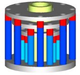
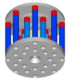
I'll do some more thinking on this subject. Here's some food for thought... a model of the three gap motor... I think it needs to be a bit larger in diameter to accomodate three gaps. This version only has provisions for a ~3.25" VC.
I'm almost certain that the innertube suspension would exhibit exactly that kind of behavior... i.e., linear at best, non-linear at worst. I don't see how it could offer a constant restoring force either. I don't think a spider could for that matter either, now that you get me to thinking about it.
So, are we stuck with a traditional linear suspension? If so, then I think using the central rod in combination with either wound springs or elastic elements oriented axially would be a natural course to take. After all, we're talking about 7" of excursion here, not 7mm, and the methods used to suspend such a motor start to become closer to those used in larger scale machinery instead of small scale drivers. The Parthenon motor just might provide the room to use this type of suspension, whereas traditional smaller drivers just weren't easy to fit these springs into.
Don't worry about resonance... there is nearly an infinite number of ways to combine spring constants and preloads to achieve a desired force/deflection curve while placing the fundamental of the suspension wherever you want it. Dampers can also be used if required, though I hope that wouldn't be the case.
The electromagnetic suspension is a neat idea, but at the obvious cost of wasted power and lots of excess generated heat. I'm not really sure it would provide a constant restoring force either... as the voice coil moves, you will have a varying number of "suspension" coil turns in the gap, so the force developed will vary just as a traditional spring would... unless you have a computer track the VC position and adjust the current appropriately.
Just as you could use permanent magnets for radial positioning (an linear air bearing), you could also use them for axial spring force. A simple stack of three would act much like opposed compression springs:
____N
____S
____S
____N
____N
____S
Of course, there is still the problem with the suspension fields interacting in a bad way with the motor fields. You'd hate for your nice linear suspension to make your motor horribly non-linear.
I'll do some more thinking on this subject. Here's some food for thought... a model of the three gap motor... I think it needs to be a bit larger in diameter to accomodate three gaps. This version only has provisions for a ~3.25" VC.
Attachments
Salient Points
This is a done deal from Magura:
Make it a solid rod of 25mm diameter. supported from the back was the basic idea. Just a plain circumferential bushing....that cheap easy and proven technology.
The cone is a done deal at least in concept. I'm open to shapes.
As for suspension restoring force don't belittle Bill's idea of a tubular surround. It will have great restoring force. It depends on the hardness of the rubber measured in Durometer if I remember correctly. The castable stuff I can get is about 40 or quite soft. Many drivers use the same property rubber. This particular driver will have a cone that is outright HUGE! And keeping up efficiency will be the primary target. That means as light as possible. If we can keep it light with a balanced ( not to strong ) motor structure then it will not need to be driven by arc welders and the like.
We that is Magura, RHosch, and myself agree on the principle of a foam cored composite cone. I came up with a 0.250" or about 6mm as a good form that will holdup to machining and still not become a structural element. I propose to punch regular holes up the circumference to provide adhesion of the inner and outer layer of carbon fiber. And then vacuum press the hole mess on a turned mold. I have a large enough wood lathe to turn this outboard. Carbon fiber is not that esoteric. Try getting any cone this size and you will run into road blocks and then a great big smile when someone wants to sell it to you.
Of spiders and other sticky wickets
I can't see any straightforward way to produce a constant return force using mechanical springs. That is possible in a one way application with a high enough preload such that the force varies little over the required range of motion, but as soon as you used opposed balanced springs, the preload cancels out and you are stuck with hooke's law.
If your driver doesn't have a lot of Xmag, you kind of need a linear spider to accurately position the coil. OTOH, if you have a great deal of Xmag, you can afford to keep less control over it and spec a progressive spider, which lets you have flatter behavior across the middle.
And, if we use your idea for the spider on each end of the former (which I like even better, due to the superior control), we almost couldn't do that anyway... how do you recone a sub that's got a spider on each side of a top plate(s) gap?
A rear mounted spider could and would provide a balanced return force. I have never seen a spider that could throw 160mm but I've never seen alot of things. One could be rigged up and done in shop if you think about it a bit. We esentially need aflat spider that will allow a great deal of excusion. If I'm wrong on this I look forward to your thoughts.
Mark
Attachments
You know, that picture of the Parthenon driver/diaphram posted at HTF really get me thinking. A sub having that much displacement, speculated T/S parameters, and being so large in physical size really has no place being mounted in a box. If you want house crumbling output from a box, that is (relatively) easy enough to accomplish using a few of the already available Tumult/AV15/Aurasound drivers. Do you really need 50 times the displacement of the Tempest driver in an enclosure? Of course not.
IB mounting was listed as a possibility, but even that is going way extreme. It doesn't make a good price/performance candidate, and that is typically what IB applications are about (aside from the obvious sound quality aspect), since manifold mounting essentially removes the space/size restrictions of a typical box. Want more output? Buy more Tempests, AV15's, or PE DVC's. Why spend $5k for a single Parthenon (or more?) when you have plenty of room to use the easier to handle, more efficient (assumption), and cheaper drivers already available?
That leaves the dipole application. Now here is where it grabs my interest. In a dipole speaker, displacement is at a premium and so is size. Not many people want a wall of a dozen subwoofers next to their main cabinets (well... perhaps we all do, but a commercial offering is going to have a hard time selling such a competent dipole cabinet... reference the Audio Artistry Beethoven Grand as the only example I'm aware of). Getting dozens of liters of displacement out of a single driver (or pair...) would be ideal for a dipole application. With that much raw displacement, you might not even need a baffle to extend low frequency response...
Which is where my train of thought has come to rest. This driver looks like a match made in heaven for the ultimate dipole subwoofer (duh). At roughly a 24" cube in floor space/volume, it is roughly what a traditional dipole W or H frame sub would occupy, though with far greater output potential. Which, interestingly enough, might shape the way the basket/diaphram, surround should be designed. What is the purpose of a basket in a traditional speaker? To hold the suspension and motor assembly, and provide attachment points for a baffle and surround. If a large displacement driver, such as the Parthenon, doesn't require a baffle for operation, then it doesn't require a surround either. And, if the suspension can be mounted from the motor assembly, there is no need for a basket at all. You simply need an integral radial and axial suspension built into the motor assembly, to which a diaphram attaches. The whole thing can be mounted free-air from the motor itself, just as is shown in the HTF/CES Parthenon pic.
It's the only application that needs such a monsterous driver (except for the car SPL guys, I'm sure). It might well be the only application the motor can be easily adapted for. Why not focus our DIY design efforts toward that end?
Rhosch,
A very practical point.
I say that with a sigh because I am admittedly an extremist who entertained notions of using this driver in a home IB or a large linkwitz-transformed or ELF alignment.
But I must grudgingly agree that this idea may be best suited for dipole only--at least for now. Not least among its charms, this way we can cut the gordian knot of the surround question.
If we're talking pure velocity transducer now, we'll have to remember to be specifically picky about self-noise issues, since there's no box to muffle them. These include both suspension/motor mechanical and airflow noises and diaphragm edge vortices.
Perhaps after we refine the velocity transducer version, we could consider ways of retrofitting a basket/surround for a pressure-transducer version. I can't bring myself to entirely rule it out yet...
Variac,
I'm with you on that. Sorta what I suggested...
I'm with you on that. Sorta what I suggested...
Or, why not skip the rod entirely and just put three "dimples" of bushing material around the inside of the bottom of the VC former, and call the pole piece our "rod?"
- Status
- This old topic is closed. If you want to reopen this topic, contact a moderator using the "Report Post" button.
- Home
- Loudspeakers
- Subwoofers
- DIY Parthenon