Mwmkravchenko and I have agreed to put some serious thought toward how normal people might make something like the extreme-excursion Adire Parthenon relatively simply in a home shop, or at least with a minimum of expense.
Since CES 2004 hasn't yet happened, we don't yet know how Adire has contrived to harness this motor with a high-excursion suspension, but we'd like to brainstorm simple, homespun ways of expanding the frontiers of extreme diaphragm excursion.
We don't yet know where this experiment will take us, but that's at least half the fun, right? In the end, I hope the moral of the story will be that normal people like you and I can, indeed, design and build high-performance audio transducers--the final frontier of DIY audio!
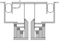
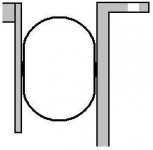
That said, here's my first stab at how we might accomplish this. (Sorry for the quick 'n dirty drawing, but I hope it's clear enough.)
At the bottom, we have a three-gap version of the Parthenon motor with a 4" dia. pole piece, using similar construction methods.
The suspension will be the tough part--here goes.
First of all, we have to essentially abandon the classic spider/half-roll-surround suspension model. It just isn't the way to go when you're looking for 3+" of one-way Xsus, IMHO. To center the VC in the gap radially, I suggest three small rollers mounted to the top of the pole piece, on which the inner surface of the VC former rides.
Serving double duty as spider and surround, I suggest . . . wait for it . . . a common bicycle tire tube! With an extension, the inflating stem would feed through the diaphragm, and you could inflate the tube to a variety of pressures, which would supply a variety of compliance curves. The molded shape of the tube would supply the return force toward zero VC excursion. As a bonus, the internal pressure would allow it to be both supple and immune to suck-back.
To be continued...
Bill
Since CES 2004 hasn't yet happened, we don't yet know how Adire has contrived to harness this motor with a high-excursion suspension, but we'd like to brainstorm simple, homespun ways of expanding the frontiers of extreme diaphragm excursion.
We don't yet know where this experiment will take us, but that's at least half the fun, right? In the end, I hope the moral of the story will be that normal people like you and I can, indeed, design and build high-performance audio transducers--the final frontier of DIY audio!
That said, here's my first stab at how we might accomplish this. (Sorry for the quick 'n dirty drawing, but I hope it's clear enough.)
At the bottom, we have a three-gap version of the Parthenon motor with a 4" dia. pole piece, using similar construction methods.
The suspension will be the tough part--here goes.
First of all, we have to essentially abandon the classic spider/half-roll-surround suspension model. It just isn't the way to go when you're looking for 3+" of one-way Xsus, IMHO. To center the VC in the gap radially, I suggest three small rollers mounted to the top of the pole piece, on which the inner surface of the VC former rides.
Serving double duty as spider and surround, I suggest . . . wait for it . . . a common bicycle tire tube!
With an extension, the inflating stem would feed through the diaphragm, and you could inflate the tube to a variety of pressures, which would supply a variety of compliance curves. The molded shape of the tube would supply the return force toward zero VC excursion. As a bonus, the internal pressure would allow it to be both supple and immune to suck-back. To be continued...
Bill
Attachments
EXTREME AUTOSOUND
I believe this is 24" x 24"
Couple interesting motor designs.
http://www.diyaudio.com/forums/showthread.php?s=&threadid=17936&perpage=15&pagenumber=6
I believe this is 24" x 24"
Couple interesting motor designs.
http://www.diyaudio.com/forums/showthread.php?s=&threadid=17936&perpage=15&pagenumber=6
Attachments
These super-high-excursion drivers seem to create a lot more big problems--now we have to worry about the tinsel leads breaking more, and will they bump into something and short out?
This is an intruiging idea. Neodynium is easy to come by (old hard drives, ) so creating huge magnet structures is not outside of our realm of possibility.
I look forward to what this thread brings up...
This is an intruiging idea. Neodynium is easy to come by (old hard drives,
) so creating huge magnet structures is not outside of our realm of possibility.I look forward to what this thread brings up...
I thik that the leads could be glued to the cone and run inside the surround with very flexible silicon, this would be a problem for smaller lighter drivers but i dont think some leads on the surround would even make a dent in this beasts SPL performance.http://www.diyaudio.com/forums/showthread.php?threadid=21398&goto=newpost
Hi,
I can't vision the inner tube idea too well. Since you have the three tiers available, EM suspension would seem to slot in nicely. From my preliminary tests, it seemed to work quite well. Off course we're talking extreme excursion here so I don't know the practical feasibility; perhaps with a failsafe surround to prevent the former from popping out/hitting the bottom plate.
I'm wondering how much noise rollers would introduce in a transducer though...
Attachments
I believe that a regular spider and surround could infact be used, it would just have to be alot bigger... like, a 12inch diameter spider, and a 4inch wide surround... I admit, the surround would be impractical, but a spider of this size is quite feasable... also, a CONE for the speaker "cone" would be much stronger and lighter than a flat one... probably harder to make, but maybe it should be a consideration...
ooo ooo, furthering EM suspension, by increasing the winding height of the two suspension VC's so that they span greater than the distance between tiers, at high excursion two tiers will be acting on the suspension VCs still. The downsid being the increased height of the first tier from the bottom plate, more wire/weight bla bla...
it would appear, (considering the 4inch VC instead of the original 3inch, and the 3 sets of coloums, rather than the current 2) that this motor assembly would be somewhere near 12inches in diameter.... lol anyone see a possible problem with that? lol  you'd just HAVE to go with atleast a 30inch cone with a magnet of that size hanging off the back.. lol am I the only one that finds that slightly insane??? LETS DO IT!!! heh
you'd just HAVE to go with atleast a 30inch cone with a magnet of that size hanging off the back.. lol am I the only one that finds that slightly insane??? LETS DO IT!!! heh 
Glad to see many of you are interested in this project!
I look forward to batting around some more ideas. Already I think we're onto something with jacketed leads. Now how to string them...
I'm hoping Mwmkravchenko will join us and share some of his ideas about suspension, etc. His challenge is what nudged me to start this thread.
Vikash, interesting idea with the EM suspension. However, I'm suspicious it may be far better suited to lower-excursion applications. I'd always thought of it as working in tandem with ferrofluid to position the VC radially, (and reap the benefit of going spiderless) but ferrofluid is out of the question here, IMHO.
Also, in this app, there are the added difficulties of the necessary VC weight and the heatsinking for the large DC current the EMS coils would have to pass to keep control of this heavy diaphragm. And even if you were to use EMS, you would still need a surround to seal the basket/diaphragm juncture.
Now, to explain my bicycle tube suspension:
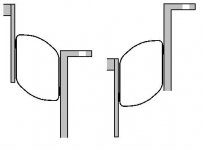
My first pic above was really too small to allow you to see much detail in the innertube suspension, so here's a blow-up.
As you can see, I'm thinking of attaching the tube at two small points along its inner and outer midline. This allows the tube to roll freely between the edge of the diaphragm and the basket in a large range of axial motion.
I look forward to batting around some more ideas. Already I think we're onto something with jacketed leads. Now how to string them...
I'm hoping Mwmkravchenko will join us and share some of his ideas about suspension, etc. His challenge is what nudged me to start this thread.
Vikash, interesting idea with the EM suspension. However, I'm suspicious it may be far better suited to lower-excursion applications. I'd always thought of it as working in tandem with ferrofluid to position the VC radially, (and reap the benefit of going spiderless) but ferrofluid is out of the question here, IMHO.
Also, in this app, there are the added difficulties of the necessary VC weight and the heatsinking for the large DC current the EMS coils would have to pass to keep control of this heavy diaphragm. And even if you were to use EMS, you would still need a surround to seal the basket/diaphragm juncture.
Now, to explain my bicycle tube suspension:
My first pic above was really too small to allow you to see much detail in the innertube suspension, so here's a blow-up.
As you can see, I'm thinking of attaching the tube at two small points along its inner and outer midline. This allows the tube to roll freely between the edge of the diaphragm and the basket in a large range of axial motion.
Attachments
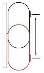
Here's an illustration of how the tube would allow large excursions.
Varying inflation pressure would alter the tube's diameter, thereby altering its compliance curve.
Since the tube was molded in a torus, the inner diameter is naturally smaller than the outer. Therefore, the elastic property of the tube's inner diameter will supply a measure of return force as excursion tends to turn it inside out.
Since the tube supplies radial centering of the diaphragm, return force against excursion, and seals the basked/diaphragm juncture, it functions as both spider and surround.
Attachments
Hello, Bill... you continue to rule!
My hypothesis was something more akin to an old 2-way door hinge, like an old saloon door (as I stated on CAT) - applied to a surround.
I drew a picture, attached to this post.. pardon the poor artistry.
I don't think the tube will work... my basis for that is the old Earthquake passive radiator.
It was a nifty rigid flat panel, suspended with two back-to-back half-roll surrounds.
So why my doubt? One of the half-rolls (the bottom one) had holds drilled through it every few inches, to allow air to escape... because the changing shape meant changing air pressures. The higher the excursion, the less space inside.
If it were pressurized, wouldn't that limit your excursion?
As regards CES and XBL^2...
I just wanted to point out that CES is going to be doubly exciting in the scope of high-excursion motors!
Not only is Adire bringing a fully functioning 24"x24" driver using the XBL^2 Parthenon motor that they've developed...
...but Resonant Engineering is also bringing an XBL^2 subwoofer, with 80+mm... utilizing a 24"x24" panel.
I'm particularly interested in the RE driver to see if it is a distinct XBL^2 design, or simply a Parthenon.
Mostly, I'm interested in the suspensions for these two drivers.
I understand how XBL2 can be architected to yield obnoxious excursion... I'm excited to see how it's realized in application with a suspension that can keep up.
Linesource...
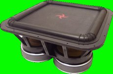
The unfortunate thing with the Quadrasub (besides it's price tag and questionable range of applications) is that it has four VC formers all tied to it, which would seem to make it quite intolerable of any assymmetry of the forces each VC makes... which would limit excursion, or rather make higher excursions a riskier affair.
I'm not sure why they chose to use a solid diaphragm, when they could have simply sectioned that rigid diaphragm into four sections, rejoined by gluing a rubber or foam "tape" across the cuts.
That would at least allow a mm or two of variance, allowing each motor to behave individually, while still allowing the four motors to work together, essentially pushing one single 24"x24" diaphragm together.
Oh well.
My hypothesis was something more akin to an old 2-way door hinge, like an old saloon door (as I stated on CAT) - applied to a surround.
I drew a picture, attached to this post.. pardon the poor artistry.
I don't think the tube will work... my basis for that is the old Earthquake passive radiator.
It was a nifty rigid flat panel, suspended with two back-to-back half-roll surrounds.
So why my doubt? One of the half-rolls (the bottom one) had holds drilled through it every few inches, to allow air to escape... because the changing shape meant changing air pressures. The higher the excursion, the less space inside.
If it were pressurized, wouldn't that limit your excursion?
As regards CES and XBL^2...
I just wanted to point out that CES is going to be doubly exciting in the scope of high-excursion motors!
Not only is Adire bringing a fully functioning 24"x24" driver using the XBL^2 Parthenon motor that they've developed...
...but Resonant Engineering is also bringing an XBL^2 subwoofer, with 80+mm... utilizing a 24"x24" panel.
I'm particularly interested in the RE driver to see if it is a distinct XBL^2 design, or simply a Parthenon.
Mostly, I'm interested in the suspensions for these two drivers.
I understand how XBL2 can be architected to yield obnoxious excursion... I'm excited to see how it's realized in application with a suspension that can keep up.
Linesource...
The unfortunate thing with the Quadrasub (besides it's price tag and questionable range of applications) is that it has four VC formers all tied to it, which would seem to make it quite intolerable of any assymmetry of the forces each VC makes... which would limit excursion, or rather make higher excursions a riskier affair.
I'm not sure why they chose to use a solid diaphragm, when they could have simply sectioned that rigid diaphragm into four sections, rejoined by gluing a rubber or foam "tape" across the cuts.
That would at least allow a mm or two of variance, allowing each motor to behave individually, while still allowing the four motors to work together, essentially pushing one single 24"x24" diaphragm together.
Oh well.
Attachments
When will I learn to keep my big mouth shut???
I guess I'm up to my ankles in doo doo the only question is did I jump in head or feet first??
OK musings on musings. I have seen and worked on linear motor assemblies for older disk drives ( remember the days when 3 gigs was HUGE ) yes those kind of disc drives. They had a 4.5" long edge wound voice coil that was bearing guided. It had the most enormous magnet system I have ever seen and about 3.5" total throw that was controlled. The only problem with the system was the NOISE LOTS OF IT. I tried to make it quiet but could not succeed.
But I like your surround idea. The only part that I have a problem with is in the actual adhering the "inner tube" to the basket and the diaphram. It must be both mechanical and glued to survive the stress. My physics is a bit rusty but there is an awfull lot of excursion therefore the potential for not a bit of kinetic energy that must be absorbed by the surround. Maybe absorbed is incorrect. But at least the surround must be able to survive the force imparted by the motor amp system and be able to keep the diaphram from flying off into lala land.
The idea of controlling the compliance is also interesting but is it totally feasable. Inner tubes leak. Not through the tube but through the valve. It may be more realistic to find a golden mean that would allow the best of what there is to offer.
Remember a driver like this could be used boxed, ported in a box or as a dipole. Each would need an ideal compliance to function at it's peak.
As for leaks I guess that is what a valve cap is for. ( problem solving in reall time ) ( I'm so good I impress myself ) LOL
I have rambled on enough. Lets toss this ball around a bit more and see if we can come up with something a little more concrete. The super-X must be convertable to what ever we come up with in the terms of a surround, spider assembly.
The motor structure ( I think therefore jump in at anytime ) is a thought out work that Bill has come up with. Maybe if we pick his brain he'll give us some of his best thoughts on the subject.
Mark
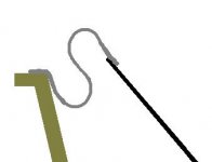
Here's an idea I had a long time ago as a surround for this thing.
What you would do is have two slinkies, one slightly larger in diameter that the other. Between them would be a piece of stiff cloth that is air tight. It will look a little like this:
Dan told me that this has been done before a long time ago, so there is no patent possibility. But I think with some ingenuity it would work quite well. The downfall is that it would need a custom basket, but the Parthenon already needs one. The advantage is that you won't have to worry about losing Sd from the surround.
What you would do is have two slinkies, one slightly larger in diameter that the other. Between them would be a piece of stiff cloth that is air tight. It will look a little like this:
An externally hosted image should be here but it was not working when we last tested it.
Dan told me that this has been done before a long time ago, so there is no patent possibility. But I think with some ingenuity it would work quite well. The downfall is that it would need a custom basket, but the Parthenon already needs one. The advantage is that you won't have to worry about losing Sd from the surround.
Hi Geo,
Nice to have a real, true-to-life XBL licensee in the mix. I'm counting on you to keep us on track especially when get back to talking about the motor.
Interesting take on the surround--sort of a crunched sinusoidal (is that a techincal term?). Looks like it certainly could allow good excursion.
My only question (and this goes for Steven's version, too) is how much radial centering force it would contribute. Even if your VC former has a good spider or some other means just above the top of the motor to center the coil radially in the gap, if your surround allows the diaphragm sideways play, the former gets rotated off-axis and your coil will end up kissing the motor at some point (especially in one so deep & multiple-gapped). I'm not saying that your surround wouldn't be good on this point, just that that's a question that pops into my mind. Have you ever mocked up your idea and tested it?
Yep, the earthquake PR was my inspiration...
Yeah, I'd thought about that. IF the enclosed space has a circular cross-section, you are right that any excursion would distort it and change its volume, as I believe is the case with the Earthquake. But if you sqeeze that circle between the diaphragm and basket and connect it at two narrow bands like I'm proposing, you get an oval that can roll through a lot of excursion before there's any deformation/change in volume. My previous illustration wasn't ideal since it shows the shape of the innertube as it surpasses Xsus and goes nonlinear. Below is an illustration of how I picture it working within its linear limits. Notice there's a large range of motion with no deformation. It's just my theory right now, but I hope that's how it'll work in real life.
In this application, I believe the inflation pressure would pretty much just change the volume of the tube, which in turn affects the dimensions and the elastic pre-load on the rubber. So you might inflate it more if you want more excursion, but you'd also be stiffening the suspension. There's a bunch of variables here, so we'd have to run some emperical tests to really know how well it'll work.
Nice to have a real, true-to-life XBL licensee in the mix.
I'm counting on you to keep us on track especially when get back to talking about the motor.Interesting take on the surround--sort of a crunched sinusoidal (is that a techincal term?
). Looks like it certainly could allow good excursion. My only question (and this goes for Steven's version, too) is how much radial centering force it would contribute. Even if your VC former has a good spider or some other means just above the top of the motor to center the coil radially in the gap, if your surround allows the diaphragm sideways play, the former gets rotated off-axis and your coil will end up kissing the motor at some point (especially in one so deep & multiple-gapped). I'm not saying that your surround wouldn't be good on this point, just that that's a question that pops into my mind. Have you ever mocked up your idea and tested it?
I don't think the tube will work... my basis for that is the old Earthquake passive radiator.
Yep, the earthquake PR was my inspiration...
One of the half-rolls (the bottom one) had holds drilled through it every few inches, to allow air to escape... because the changing shape meant changing air pressures. The higher the excursion, the less space inside.
Yeah, I'd thought about that. IF the enclosed space has a circular cross-section, you are right that any excursion would distort it and change its volume, as I believe is the case with the Earthquake. But if you sqeeze that circle between the diaphragm and basket and connect it at two narrow bands like I'm proposing, you get an oval that can roll through a lot of excursion before there's any deformation/change in volume. My previous illustration wasn't ideal since it shows the shape of the innertube as it surpasses Xsus and goes nonlinear. Below is an illustration of how I picture it working within its linear limits. Notice there's a large range of motion with no deformation. It's just my theory right now, but I hope that's how it'll work in real life.
If it were pressurized, wouldn't that limit your excursion?
In this application, I believe the inflation pressure would pretty much just change the volume of the tube, which in turn affects the dimensions and the elastic pre-load on the rubber. So you might inflate it more if you want more excursion, but you'd also be stiffening the suspension. There's a bunch of variables here, so we'd have to run some emperical tests to really know how well it'll work.
Attachments
Two cents from the side.
I dont know what sort of tube you expect to use, but you will have to sort out two problems:
1) The tube will take up a lot of energy....it stretches as well as rolls. Besides that its not common to see tubes cast of high quality, so the tube walls are not even.
2) The tube will not be able to keep the pressure as is. Any tube ive seen till date looses the pressure over time (through the tube and the valve)....and thats fairly fast.
I like the idea of a tube though, and the problems stated above can be solved im sure.
Magura
Mark,
I agree there's potential for noise from the rollers guiding the VC former. I'm hoping that if the rollers were rubber where they contact the former, it shouldn't make noise. I'm open to any other suggestions of how we could get radial centering with infinite compliance.
Yes, I agree. That adhesion will have to be very robust. It'll take some experimenting.
Vikash's earlier comments remind me of one other possible thing we could try to take stress off the adhesion: We might rig up a couple of braking coils mounted above the top gap and below the bottom one to absorb most of the kinetic energy before it stresses the suspension.
I agree there's potential for noise from the rollers guiding the VC former. I'm hoping that if the rollers were rubber where they contact the former, it shouldn't make noise. I'm open to any other suggestions of how we could get radial centering with infinite compliance.
But I like your surround idea. The only part that I have a problem with is in the actual adhering the "inner tube" to the basket and the diaphram. It must be both mechanical and glued to survive the stress.
Yes, I agree. That adhesion will have to be very robust. It'll take some experimenting.
Vikash's earlier comments remind me of one other possible thing we could try to take stress off the adhesion: We might rig up a couple of braking coils mounted above the top gap and below the bottom one to absorb most of the kinetic energy before it stresses the suspension.
- Status
- This old topic is closed. If you want to reopen this topic, contact a moderator using the "Report Post" button.
- Home
- Loudspeakers
- Subwoofers
- DIY Parthenon