You may have noticed that the arm can rotate around the horizontal axis, and that this is prevented/controlled by a rubber band.
I don't understand the concept at all. Please elaborate. Thanks!
The usa patent + drawing is around on the web too, Thomas is a creative guy, admire his products.
I thought the arm is a Frank Schroeder creation.

.
I don't understand the concept at all. Please elaborate. Thanks!
I thought the arm is a Frank Schroeder creation.
.
From the visible detail I thought it was an April Fool Prank.
BillG
I don't understand the concept at all. Please elaborate. Thanks!
I thought the arm is a Frank Schroeder creation.
.
Please accept my apologizes , direct driver
However , Both Frank & Thomas are creative guys
will try to find the patent drawings , for the fanatics .
THX
Paul
Hi,
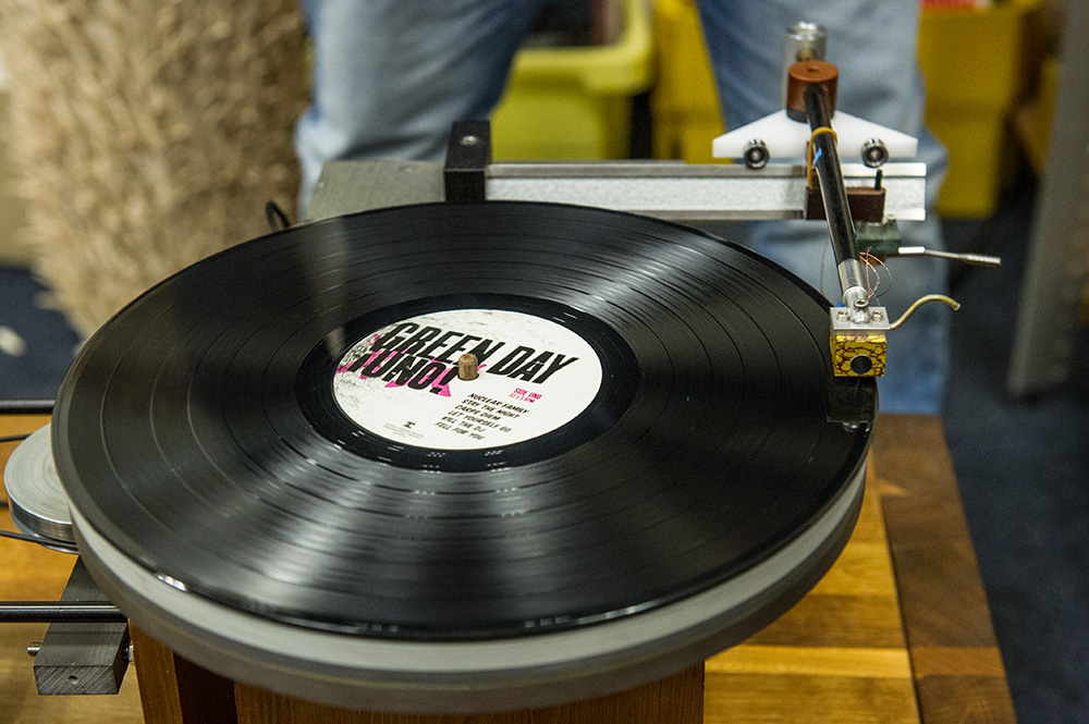
Just a few features of the pictured arm(which is obviously not related to my patented pivoted linear tracing arm).
The bearing level is on the record level.
The eff. mass in the horizontal plane is about the same as the eff. mass. in the vertical plane - a first for a straight line passive linear tracker.
Why? When you look at the carriage closely, you'll find the arm to feature an additional, "pivoted" lateral bearing, the "0"-position(perfect tangency) of which is governed by a rubber band(can be done differently: spring, magnets.... too). This allows the arm to rotate around a vertical axis, decoupling it from the carriage for fast/eccentric movement.
The rubber band generates a vertical load on the bearing, reducing friction and excluding chatter. It can be moved to tune the fres in the lateral plane.
The main armwand will NOT remain perfectly tangent at all times, but the force required(generated by cantilever displacement) to move the carriage is as low(if not slightly lower)than in "conventional" SLLT arms. Typically, the deviation is below 0,5°, lower once better bearing have been installed.
The (front to back-)displacement of said horizontal bearing(it sits quite a bit behind the linear edge) allows for just a small/light counterweight to be used(aluminum in this case), the total weight is rather low for such a "long"(~200mm eff.) arm.
Not prone to warp wow.
Slightly eccentric records put far less stress on the cantilever.
There's more, but that should suffice for now.
No April fools joke, too early for that....
Cheers,
Frank Schröder
Last edited:
Frank,
It's a neat idea but I see it as acting similar to a passive servo in performance as the tail wagging the dog. Better bearings will improve things but in my experience with longer arm wands there was more stress placed on the stylus than a shorter arm, plus the fact that speed seemed to be slowed down along with the arm itself leaving more of a sonic impriint.The only benefits will be less warp wow and effective mass being similar in lateral and vertical planes but this can be worked with on the arm as we have here. I have found that the more rigid the coupling and design becomes the better the sound improves especially in the lower regions with much better defined and refined bass through to mids, versus a less stiff rigid coupling/design. Or maybe my ears are just acutely sensitive to tangential deviation?, and mistracking. I find warp wow a non issue except very badly warped records, which are more of a torture test tool for tracking.
Colin
Hi,
Just a few features of the pictured arm(which is obviously not related to my patented pivoted linear tracing arm).
The bearing level is on the record level.
The eff. mass in the horizontal plane is about the same as the eff. mass. in the vertical plane - a first for a straight line passive linear tracker.
Why? When you look at the carriage closely, you'll find the arm to feature an additional, "pivoted" lateral bearing, the "0"-position(perfect tangency) of which is governed by a rubber band(can be done differently: spring, magnets.... too). This allows the arm to rotate around a vertical axis, decoupling it from the carriage for fast/eccentric movement.
The rubber band generates a vertical load on the bearing, reducing friction and excluding chatter. It can be moved to tune the fres in the lateral plane.
The main armwand will NOT remain perfectly tangent at all times, but the force required(generated by cantilever displacement) to move the carriage is as low(if not slightly lower)than in "conventional" SLLT arms. Typically, the deviation is below 0,5°, lower once better bearing have been installed.
The (front to back-)displacement of said horizontal bearing(it sits quite a bit behind the linear edge) allows for just a small/light counterweight to be used(aluminum in this case), the total weight is rather low for such a "long"(~200mm eff.) arm.
Not prone to warp wow.
Slightly eccentric records put far less stress on the cantilever.
There's more, but that should suffice for now.
No April fools joke, too early for that....
Cheers,
Frank Schröder
Hi Frank ,
Thanks for the clarification ! an intriguing tonearm . it sort of reminds me of the Sukara rotary headshell .
THX
Paul
It's a neat idea but I see it as acting similar to a passive servo in performance as the tail wagging the dog.
I think Frank's concept IS to reduce the tail wagging the dog effect. Regarding the "passive servo" term, a servo system is active, not passive and in fact a servo system is indeed to eliminate the tail wagging the dog effect (high horizontal mass) at the expense of rigid tangency through out the record. A bit of compliance built into the system is not a bad idea. I guess I have to hear it side by side to see if there's trade-off.
Once again, Frank is always thinking outside of the box, even after the achievement of the innovative LT arm. Frank, you're always one step ahead of me (or us)!
Directdriver,
Perhaps I need to be clearer on what I mean by a passive servo conceptually. I am aware that a servo is an active system, but what to imply here is that it's movement akin to a servo. First the arm will go out of tangent, then the rubber bands stored energy will move the bearing system over in a step, mass of this will determine the overshoot or undershoot which comes down to do we damp this now?.
It may have the potential to work very well, I'm thinking I'll even knock one up just to see. It's just a different approach to the same quest, I'm not shooting down the concept at all just we are not confused here. Btw, Directdriver, how are the builds going?
Colin
Perhaps I need to be clearer on what I mean by a passive servo conceptually. I am aware that a servo is an active system, but what to imply here is that it's movement akin to a servo. First the arm will go out of tangent, then the rubber bands stored energy will move the bearing system over in a step, mass of this will determine the overshoot or undershoot which comes down to do we damp this now?.
It may have the potential to work very well, I'm thinking I'll even knock one up just to see
. It's just a different approach to the same quest, I'm not shooting down the concept at all just we are not confused here. Btw, Directdriver, how are the builds going?Colin
Thanks for the link. The ever more inventive Frank is at it again! Here's the picture!
few pages back , I wrote exact type of V groove bearings , most probably adequate for bearings on knife approach
Colin
At audio frequencies your arm already has similar effective masses in the horizontal and vertical planes without needing to add any additional mechanisms to achieve it. I briefly went over this point all the way back on page 136. I've popped it in again here to save time.
Don't worry about effective mass not being the same. On records low frequencies below 200hz are mono, lateral modulation only. Furthermore at audio frequencies lateral movements of the arm are very small, less than a couple of microns. If they weren't you'd really hear it. At audio frequencies the arm does not move straight side to side, rather it rotates about its centre of mass. A one micron movement at the cartridge on a 75mm arm twists the arm through less than a thousandth of a degree. No arm has less than that degree of play. Nature always take the lowest energy option. It takes less energy to ratate than to linear translate by the same distance at the cartridge. The effective masses when measured about the centre of mass of the carriage are going to be nearly the same.
Niffy[/QUOTE]
The full mass of the carriage only act as the horizontal effective mass at very low frequencies and would only be problematic with unnaturally off centred records.
I fully agree that a more rigid coupling makes for a better sound.
Frank
I've looked at a couple of websites of your designs. It's great to see someone who refuses to think inside the box. Without people like you we'd only have products and designs that followed the "that's how it's always been done" approach. We wouldn't be reading this as no one would have thought "a linear tracker, that's a neat idea".
Niffy
First the arm will go out of tangent, then the rubber bands stored energy will move the bearing system over in a step, mass of this will determine the overshoot or undershoot which comes down to do we damp this now?
Thanks for clarifying. Yes, in this case it does resemble a "passive" version of a servo, that is, a corrective system using mechanical means, not electronic. Although I don't think Frank's design is trying to be servo or corrective, and I think "compensating" is a better word. It still does its job as a parallel tracker and in the case of less than ideal record condition, it just lessens the damage. I think the upside with Frank's system is that while it's not tangential tracking in the most rigid way but the leniency in dealing with off-centered records and warp due to longer arm and at record level has a lot of benefits and probably longer lifespan on cartridge suspension and cantilever. With a perfectly centered and flat record, it should track tangentially. Nothing is perfect and I'm not a perfectionist, more of a pragmatist. That's why I can never own an airbearing arm, not even airpump for fish!
how are the builds going?
Currently I'm not much of a builder so you can say I can't walk the talk. This is purely intellectual exercise for me right now. Until my friend build his machine shop, I have to settle on modifying tube amps to satisfy my tinkering. I would love to play with tonearms one day though. Your thread is excellent
 and makes my hands itch!
.
Hi Guys ,
I don't wanna spend time going through my record collection and rejecting my off-centered samples for the expence of a bit stress on the cantilever , however excentric records + lateral cantilever movement it is a valid point to keep in mind when disscussing tonearm design . Frank seems to be the first arm designer who have actualy took the change to work this out in a way that we have not seen before ( correct me when wrong ) and deserves the credits for this .
Personaly I think that the extra lateral pivot is a smart way to fight the lateral cantilever movement , but at the same time I'm wondering how much of a degree is making it a better sounding tonearm in reality . also .. creating an
additional bearing pivot could be very tricky and could do more harm than good when not executed perfectly , i.e. extremely low bearing play I'd think . I'm also curious what kind of bearing has been used here .
That rubber band must have something to do with compliance and bringing the arm back to tangial position , sort of compensation of the lateral movement . rubber is also being used for dampening properties I guess .
Realy interesting , and I hope to read some more about this arm soon .
THX
Paul
I don't wanna spend time going through my record collection and rejecting my off-centered samples for the expence of a bit stress on the cantilever
, however excentric records + lateral cantilever movement it is a valid point to keep in mind when disscussing tonearm design . Frank seems to be the first arm designer who have actualy took the change to work this out in a way that we have not seen before ( correct me when wrong ) and deserves the credits for this . Personaly I think that the extra lateral pivot is a smart way to fight the lateral cantilever movement , but at the same time I'm wondering how much of a degree is making it a better sounding tonearm in reality . also .. creating an
additional bearing pivot could be very tricky and could do more harm than good when not executed perfectly , i.e. extremely low bearing play I'd think . I'm also curious what kind of bearing has been used here .
That rubber band must have something to do with compliance and bringing the arm back to tangial position , sort of compensation of the lateral movement . rubber is also being used for dampening properties I guess .
Realy interesting , and I hope to read some more about this arm soon .
THX
Paul
Last edited:
Addition pivot point makes system that is compound pendulum with associated vibrational modes, that has mass of cantilever, mass of arm, and mass of sled. Indeed more to think about in terms of being able to add damping system at arm/sled pivot point, a point highly accessible, unlike pivot at cantilever/cartridge junction.
Off center records: Center spindle could be placed on two axis servo and feedback from rpm of TT and LF signal from cartridge used to correctly center record. Undoubtedly a colossal DIY project. Signal logic could be used to reject integration of lead in spiral, inter track spiral, and lead out spiral.
Off center records: Center spindle could be placed on two axis servo and feedback from rpm of TT and LF signal from cartridge used to correctly center record. Undoubtedly a colossal DIY project. Signal logic could be used to reject integration of lead in spiral, inter track spiral, and lead out spiral.
Just a quick couple of question. I don't recall seeing any mention in this thread so far about arm wiring. It may have been discussed before but I don't fancy trawling through 150+ pages to find out. What type are you using? How are you running it to prevent mechanical drag. The wire in the posted pictures looks very thin and appears to be unsheilded. If it is unsheilded how do you prevent hum?
Niffy
Niffy
Just a quick couple of question. I don't recall seeing any mention in this thread so far about arm wiring. It may have been discussed before but I don't fancy trawling through 150+ pages to find out. What type are you using? How are you running it to prevent mechanical drag. The wire in the posted pictures looks very thin and appears to be unsheilded. If it is unsheilded how do you prevent hum?
Niffy
Niffy,
A couple of quick and possibly irreverent answers. Yes, it is very thin. Enameled copper magnet wire #30 or smaller AWG, I didn't measure it. I give one pair a loose right hand twist and the other pair a loose left hand twist and then an even looser twist to the 2 pairs, just to keep things more or less together. I make them long enough to flex easily and hang the far end with connectors from a hook in the compartment ceiling above the TT. Hummmmm! I turn the volume down to a point where I cant hear the hum. Then I turn the volume down some more so I won't damage my ears from the music. Nuff said.
BillG
Hi,
To answer - or comment on few questions/issues that popped up:
Long or short, on a conventional straightline tt arm the cantilever needs to be displaced to overcome stiction/rolling friction. For most of its operating time, tangency is what you see looking at the armwand, but not when observing the cantilever.
One is definitely NOT tracing the record as it was cut (in a strict geometric sense).
Try an airbearing arm and that problem disappears, well, kind of, as the high eff. lateral mass will cause low frequency oscillation. Wiring and deviation from level will preload the cantilever. A small amount of damping(lateral plane only) is recommended...
The arm shown was put together as an example what can be done with standard parts and fairly quickly too.
The bearings for the lateral pivot are preloaded by the rubber band. There is no slack and the contact is more "rigid" than on any Cantus clone(I understand that it is part of the working principle, don't worry
Eccentric records are not the reason to implement an additional lateral bearing. It's all about reducing any additional lateral load on the cantilever AND allowing for the arm to move smoothly most of the time.
The rubber band can be moved relative to said lateral pivot and one can tune the lateral fres. It is EXACTLY because bass is cut laterally that this is an advantage.
You can de-tune the lateral fres to avoid exitation by multiples of the suspension res or an "Eiffeltower" res(heavy turntable plus amps or whatever on top of a rack, worse if it is standing on a wooden floor).
I did not use V-groove bearings, even though I have some that would work o.k. The "bottom" of the V-groove isn't nearly a well finished(or as hard) as what I used: the inner race of a high quality ball bearing(with another bearing inside, offset to prevent chatter).
Don't get me wrong, I never intended to "show anyone how it's done" or mean to compete with other straightline tt arm.
This was build for a non-commercial, fun event that called for everyone to use a cheap IKEA sourced CD shelf to build an audio replay device, any type(speakers, amps, sources, even a DAC were brought to the party)
I will bring an improved version to the next DIY event(Frickelfest) in June....
Have a fun weekend,
Frank
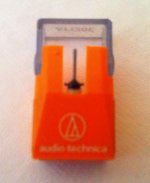
Pic of stylus
Here is a pic of the stylus I have been using frequently for every variation of arm, I think this can put to rest the stress on cantilever theory, not even slightly skewed, even at 30 grams lateral mass I can't even visibly see the stylus displaced on off center records. Keeping in mind an air bearings arm is atleast 50 plus grams of lateral mass, terminator is 70 plus grams.
My vinyl has seemed to stay quiet even longer than with a pivoted arm, and I've noticed an absense of obvious wear vs prior pivoted arms with antiskate.
Frank, you make beautiful arms, they are amazing pieces of work, perfect?, probably not since no arm is. I unfortunately cannot afford the entry fee of 3900 dollars to start tasting shroeder arms, but the cost to build this wheeled arm alone financially let's it run circles around the unaffordable to many offerings.
Reasearch is expensive however and I'm amazed anyone can still make any money in Audio, but Doing the quick math I can see why the costs are exhorbitantly high in a niche market.
Colin
Here is a pic of the stylus I have been using frequently for every variation of arm, I think this can put to rest the stress on cantilever theory
, not even slightly skewed, even at 30 grams lateral mass I can't even visibly see the stylus displaced on off center records. Keeping in mind an air bearings arm is atleast 50 plus grams of lateral mass, terminator is 70 plus grams. My vinyl has seemed to stay quiet even longer than with a pivoted arm, and I've noticed an absense of obvious wear vs prior pivoted arms with antiskate.
Frank, you make beautiful arms, they are amazing pieces of work, perfect?, probably not since no arm is. I unfortunately cannot afford the entry fee of 3900 dollars to start tasting shroeder arms, but the cost to build this wheeled arm alone financially let's it run circles around the unaffordable to many offerings.
Reasearch is expensive however and I'm amazed anyone can still make any money in Audio, but Doing the quick math I can see why the costs are exhorbitantly high in a niche market.
Colin
Attachments
A picture of a stylus, and something you can't see doesn't put to rest the resonance that exists in mass and spring system of tonearm plus carriage with cantilever suspension.
It's a real loss that you own test record, use it frequently, and do not record output. All results are anecdotal observations with no hard data.
What is precision of your test record's center location relative to track spiral?
It's a real loss that you own test record, use it frequently, and do not record output. All results are anecdotal observations with no hard data.
What is precision of your test record's center location relative to track spiral?
- Home
- Source & Line
- Analogue Source
- DIY linear tonearm