NEVER TRY TO POWER THIS AMP DIRECTLY ON 220/110V!!!
IT WILL KILL YOU.
-Because of high distortion,and complicated schematic
-Transformer block all HF frequencies to pass to primary because of high impedance.
-Not use direct on line voltage,FET's probably will blow and your speaker and probably YOU.
IT WILL KILL YOU.
-Because of high distortion,and complicated schematic
-Transformer block all HF frequencies to pass to primary because of high impedance.
-Not use direct on line voltage,FET's probably will blow and your speaker and probably YOU.
On that page, in the last 3 posts:
http://www.diyaudio.com/forums/class-d/240510-diy-good-class-d-amplifier-35.html
"250V on 8R (drop to 220V when full power) and 50V with 4R"
I got it wrong?
http://www.diyaudio.com/forums/class-d/240510-diy-good-class-d-amplifier-35.html
"250V on 8R (drop to 220V when full power) and 50V with 4R"
I got it wrong?
Directly from 220v will probably kill you, i tried,only if you put you hand close to the speaker or wires it will shock you a little,i did try something like this,but didnt work,and power will be to much to even use.
Line mains has a ground reference, so if you touch it, it goes to ground through you.
Line mains has a ground reference, so if you touch it, it goes to ground through you.
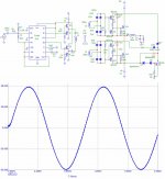
My goals are a bit different: 150W/2 ohm bridged for car subwoofer, with the highest efficiency possible. It will be a complete amp with adjustable filters LPF, HPF, bass boost and limiter. Also i have designed a semi-tracking and self-limiting power supply for it, using TL494 of course. ")
I'm looking to sell a few of these. I've found a nice aluminum case of the right size too.
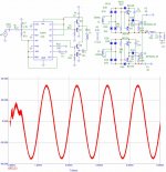
Of course, the schematics and PCB will be free for all diyaudio folks. Though it may be a while till the whole thing is done - i've had this prototype on my bench for a few months already. I don't have too much time on my hands nowadays, and when i do have time, i'm either drunk or too lazy. But it will get done. I'm listening to an early revision PCB of my amp as i post this.
I'm looking to sell a few of these. I've found a nice aluminum case of the right size too.
Of course, the schematics and PCB will be free for all diyaudio folks. Though it may be a while till the whole thing is done - i've had this prototype on my bench for a few months already. I don't have too much time on my hands nowadays, and when i do have time, i'm either drunk or too lazy. But it will get done.
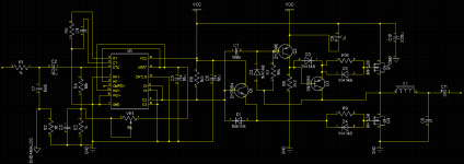
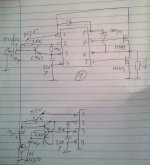
I'm listening to an early revision PCB of my amp as i post this.Here's the basic idea. Of course, for bridge, the output coupling capacitor is not needed. VR1 should be of the multiturn type. Also the bulk filter caps on Vcc can be much larger than 220u, that is just the minimum value required for stability. With smaller values amp will oscillate.
Vdd should be 8-12v above Vcc. Vcc can be 12-22v with no modifications. For higher voltages some values may need to be adjusted. Also, this driving scheme cannot be used above 25v as it will damage the upper MOSFET due to excess gate-source voltage at turn-off.
Vdd should be 8-12v above Vcc. Vcc can be 12-22v with no modifications. For higher voltages some values may need to be adjusted. Also, this driving scheme cannot be used above 25v as it will damage the upper MOSFET due to excess gate-source voltage at turn-off.
Attachments
Last edited:
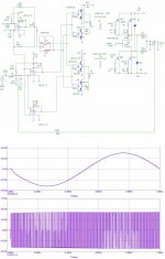
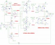
IR2153 audio modulated.
The schematic in figure (1) works, but sounds bad.
A single NPN transistor to change the capacitor charging.
Below, I have tried to change, capacitor charging and discharging. Not working.
When the RT pin have the GND potential,
capacitor should be discharged by PNP transistor.
The PNP resistor is drawn wrong, is from collector.
When the potential in B increases, NPN opens and PNP closes,
but in practice it was not so ...
---------------------------------------
If you have other ideas please put them.......
Attachments
Last edited:
- Status
- This old topic is closed. If you want to reopen this topic, contact a moderator using the "Report Post" button.
- Home
- Amplifiers
- Class D
- DIY Good Class D amplifier