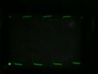
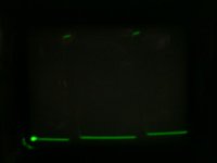
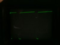
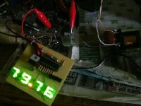
Ok,here's PWM pics and test of d3k in fullbridge mode (multimeter show voltage on speaker,in 200mV range,and last pic show frequency,I don't see reason why 80khz is bad and why go to more)
Attachments
Last edited:
Yes,when go into clipping.
I'll post when I can.What signal frequency and waveform to you like to I use when measuring?
I measure with all spectrum (25hz,50hz,100hz,200hz,500hz,1k,2k,4k,8k,16k and 20k).And I use sine wave as input,and waveform is same as input,with small noise with freq. same as switching.
I'll post when I can.What signal frequency and waveform to you like to I use when measuring?
I measure with all spectrum (25hz,50hz,100hz,200hz,500hz,1k,2k,4k,8k,16k and 20k).And I use sine wave as input,and waveform is same as input,with small noise with freq. same as switching.
Last edited:
help
Where to connect signal ground..and as you have shown positive supply voltage then why u did not indicate negative voltage..it shows ground sign..plz tell me how to connect 12v bias suply and signal ground in this amp
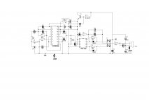
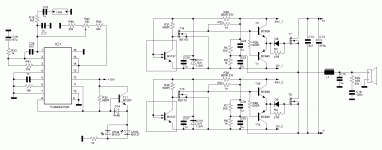
Simple amp. based on SG3525 PWM IC.
Frequency is fixed to 150kHz (fixed f is good choice) but you can modify it by changing RT/CT.
PWM is ~2-98% (which is very good).
IR2184 is HI/LO side gate driver.
Dead time provided by this IC.
Set the potentiometer on half.Turn amp ON.Set output voltage to 0V.
This amp works from first attempt
On PCB i have to use external 12V PSU for IC's
Max input voltage is +-80V.
With 4k7 adjust gain.
Output inductor is gapped core (can be used yelow toroids from AT/ATX PSU,they have internal gap.
In external 12V version you can regulate the output power only by voltage on fets.
12V is referenced to -V,not to GND!
On picture I used totem pole output instead of FET's and driver IC,but I tested wih IC and FET's too.
Where to connect signal ground..and as you have shown positive supply voltage then why u did not indicate negative voltage..it shows ground sign..plz tell me how to connect 12v bias suply and signal ground in this amp
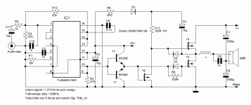
GND sign is used for amplifier ground,not power supply center tap (GND).
V/2 is used for center tap if use centertaped transformer (dual supply).If use single supply do not connect V/2 to power supply.12...15V bias supply is referenced to amplifier ground (GND sign),not to PSU ground (V/2,if use +/- supply).On first post we have schematic with regulating transistor connected,and with it,there's no need for biasing supply,as this transistor is used to do it.
V/2 is used for center tap if use centertaped transformer (dual supply).If use single supply do not connect V/2 to power supply.12...15V bias supply is referenced to amplifier ground (GND sign),not to PSU ground (V/2,if use +/- supply).On first post we have schematic with regulating transistor connected,and with it,there's no need for biasing supply,as this transistor is used to do it.
GND sign is used for amplifier ground,not power supply center tap (GND).
V/2 is used for center tap if use centertaped transformer (dual supply).If use single supply do not connect V/2 to power supply.12...15V bias supply is referenced to amplifier ground (GND sign),not to PSU ground (V/2,if use +/- supply).On first post we have schematic with regulating transistor connected,and with it,there's no need for biasing supply,as this transistor is used to do it.
Can u plz give me edited schematics showing dual supply connections?
I want to try ur amp..ordered IR2184 and i m just confused with ground issue...
Sorry for childish questions
 Maybe dead regulating transistor? What type you use?
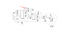
Try in this way,(see ZZZZ picture) or try other two schematics
")
Last schematic tested yesterday on my birthday party
Attachments
Last edited:
did the same as shown in second figure.,,i used c2073 as regulating transistor and supply was 25-0-25 volts...still it is no go....i want to make it works so please help me out
Try in this way,(see ZZZZ picture) or try other two schematics
Last schematic tested yesterday on my birthday party
First check do you have 12...15V bias voltage.
If have,check DC voltage at gate-source of both transistors.There will be about half bias voltage.
If have it,check DC voltage between PSU GND and speaker pin.Set it with potentiometer to about 0V
Before all tests set pot at half.
If have,check DC voltage at gate-source of both transistors.There will be about half bias voltage.
If have it,check DC voltage between PSU GND and speaker pin.Set it with potentiometer to about 0V
Before all tests set pot at half.
yes i have bias supply correct and it is 14.5v referred to negative supply..rest i will test and let u knowFirst check do you have 12...15V bias voltage.
If have,check DC voltage at gate-source of both transistors.There will be about half bias voltage.
If have it,check DC voltage between PSU GND and speaker pin.Set it with potentiometer to about 0V
Before all tests set pot at half.
Last edited:
chage opto
Hi.
i can't find opto 6N137 this in country
i can change is opto 6n135, 6n136, 6n138 or 6n139 plase recommend
thank you.
Try in this way,(see ZZZZ picture) or try other two schematics
Last schematic tested yesterday on my birthday party
Hi.
i can't find opto 6N137 this in country
i can change is opto 6n135, 6n136, 6n138 or 6n139 plase recommend
thank you.
No,because others is slow.You can only use any 10Mbd optocoupler or higher speed.Try to search 6n137 equivalent (probably HCPL series,if you can bought).I don't tested with 6N135/6n136,as it is 1Mbd,but if you like to try I will draw schematic with 6N135/6.Hi.
i can't find opto 6N137 this in country
i can change is opto 6n135, 6n136, 6n138 or 6n139 plase recommend
thank you.
By the way,with this drive you can drive almost any combination of fet's,you can use it in parallel or use one very big,as I used in subwoofer amp (I use SKM75GB123DN,IGBT
)
Last edited:
Do not let this topic..."idle"
About IR2153 amplifier outlet (high voltage) powered.
1. Why not introduce audio with an optocoupler - it may be "best" galvanic insulation
I want to say that the pulses can pass inverse into transforms.
From secondary to primary. And sourced current in mp3 or audio source.
(I do not know, I think....)
2. It would be good to identify 220V/110V CA phase using a circuit. Half-wave rectifier.
To not get the phase at GND. Safety reasons.
Last edited:
- Status
- This old topic is closed. If you want to reopen this topic, contact a moderator using the "Report Post" button.
- Home
- Amplifiers
- Class D
- DIY Good Class D amplifier