I told you from where to start ..........
you'll need to fiddle with loading resistor group (output side of C3) , to tweak for your load
in any case - leave there at least 100R , to have discharge path for C3 - useful when connecting/disconnecting speaker

True, forgot that one... but a discharge resistor is in place =)
But why would I need a loading resistor, wasn't that just something Nelson put there to reduce output impedance?
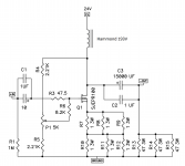
Now I've gotten new ideas and this amp is one of them I want to revisit: as with the last time I want more power without complexity so I'd thought I'd swap the CCS with a Hammond 193V ( 150mH, 1 ohm, 3A ) like they used in the Simple SIT amp.
If I've understood correctly it'd be just as easy as throwing out the active CCS and chucking in the inductor like in my picture... but since all this knowledge exists here I might as well ask =)
What I wonder especially is if the idle current isn't by default at about 2A, how do I make it so?
And if I've understood correctly the output impedance will be mostly dependant on the CCS so with the inductor it will stay high, where as passive resistors would be comparatively low?
Attachments
for Iq set - measure voltage across Rs group ;
I=U/R
set Iq with P1
output impedance will be , same as with CCS iteration , mostly dependent of Q1 ..... more precisely - slightly lower than with CCS on top
Nice.
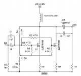
Another question though this is more academical since I'm not sure I'll actually do it: Say I wanted to celebrate the non-use of one of my heat sinks in the amp by adding another (matched) output jfet, would this be the way of doing it? Or maybe I will. Will two jfets operating at say 25W each perform better than a single one at 50W?
Attachments
Last edited:
in this case ... be sure that Pa found sweet spot for them
so , if you ask me ...... two with 100W will work better than one with 50W
")
ZM, your trying to corrupt me... and... it is... working...
Might as well try with 48V rails and 2 Jfets at the start since that is what I have configured already. Question remains if the parallel outputs schematic is decent enough to work or if there is some part missing. If I've understood it is common to add series resistance on the output to sync the output devices, is that needed in this case or is it OK since both are identical and matched?
And another thing, does the source degeneration contribute any stability to the circuit or is it only distortion reduction?
"series" resistance - you have exactly enough of that in source resistor groups
having dedicated group for each paralleled Jfet is a must .
however - when I wrote that Pa established sweet spot for them , I meant on Iq , Uds (you can alter it , but 48V will be too much ) and amount of source resistance
so - stay at no more than 24V PSU (+/-20%) and 50W max per Jfet ........ while choke will double your cards
"series" resistance - you have exactly enough of that in source resistor groups
having dedicated group for each paralleled Jfet is a must .
however - when I wrote that Pa established sweet spot for them , I meant on Iq , Uds (you can alter it , but 48V will be too much ) and amount of source resistance
so - stay at no more than 24V PSU (+/-20%) and 50W max per Jfet ........ while choke will double your cards
=)
In that case I think i'll have to stay at 1 Jfet for now since the choke can only handle 3A current... unless I get another one... in the future...
Ah, so the source resistances work in that way.
Say you only have 1 Jfet, are the source resistors still necessary or are they removable as in the F6 or simple SIT? Or hmm, I remember someone talking about that the SITs were especially well behaved when used with no degeneration, much more so than the R100 and other enhancement mode Jfets and the F6 does have a feedback loop.
Say you only have 1 Jfet, are the source resistors still necessary or are they removable as in the F6 or simple SIT? Or hmm, I remember someone talking about that the SITs were especially well behaved when used with no degeneration, much more so than the R100 and other enhancement mode Jfets and the F6 does have a feedback loop.
Last edited:
I just hooked up an F2J with a Hammond 193V as per post #482. The plan is to compare the sound of the F2J to my L'amps, they are both similar but at the same time different so will be interesting.
The 193V gives a mad efficiency boost to the F2J, my last highest power on the F2J was with 48V rails and then I got ~ 6.5W into 8 ohm. Here I use 24V rails and I get 10W clean with no higher order distortion than 2nd + 3nd into 9.4 ohm, so probably around 12W into 8 ohm. Considering that the vanilla F2J only achieves 5W into 8 ohm I guess big inductors as current sources are pretty nice =)
The current is currently 2.18A and ~ 20.5V drain voltage so about 45W dissipation on the R100 which is ok.
I just did some distortion comparisons on some speakers with the F2J ( 200 ohm in parallel instead of 15.66 so ~ 150 ohm output impedance ) vs L'amp for those who are interested in the L'amp thread.
Hmm... currently the R100 is running at 20V @2.25A => 45W... sounds a bit high or what do you others think? Heat isn't a problem, I can hold my hand on the sink indefinitely but I don't want the jfets to break in the long run =)
I have two matched pairs so I'm considering upping the source resistors to 1 ohm and then do ~ 1.2 - 1.5A on each for ~ 25-30W dissipation on each jfet. My 193V inductor is capped at 3A so I can't go higher than that.
I do have a lot of heatsinking though so I could also double the voltage to 40V at jfet drain and run each device at 35W instead. The question is if I would get power into the right impedance, the speaker is 10-20 ohm with an absolute minimum of 9.5 ohm.
Last edited:
if it's cooled properly , there is no fuss with 45W
That's good to hear, then I'll probably leave it as it is since it works so well at the moment.
When I re-built two inducted F2Js with the mod for more current I think I had the pot turned in the wrong direction and killed them both on turn-on.
So now I thought I might confirm how enchantment mode should be used to conduct 0 current. Depletion JFETs conduct close to nothing when gate is very negative compared to source, and conducts more the higher V at gate. And if I understand correctly now enchantment mode JFETs conduct nothing if source = gate, and more current the closer gate voltage is to drain voltage?
So now I thought I might confirm how enchantment mode should be used to conduct 0 current. Depletion JFETs conduct close to nothing when gate is very negative compared to source, and conducts more the higher V at gate. And if I understand correctly now enchantment mode JFETs conduct nothing if source = gate, and more current the closer gate voltage is to drain voltage?
I think I've found the culprit!
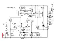
Though the main dumbness was from me =) The biasing of the F2J is of course tailored for ~ 12V drain voltage and I slammed it with 24V so even at lowest setting of pot the gate voltage got too high and the R100 tried to conduct too much current. I copied the arch nemesis bias supply instead which also has that handy zener to bring down the voltage and now it works =)
I did some tinkering first though, didn't want to blow another SS JFET so I chucked in an old IRF240 to ensure that the rest of the amp worked as intended first =)
- Home
- Amplifiers
- Pass Labs
- DIY F2 clone