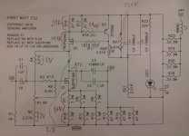
schematic with interesting node's voltages will help us to help you
Here it is:
Hmm... I'm no expert but let me guess: The voltage drop across Q2 shouldn't be that large?
Thanks for helping this little Ollboll btw =)
EDIT: R16 and R17 are each 2 series connected .47 ohm resistors.
Attachments
Last edited:
please - repeat that , more careful
just wrote voltages in nodes - against gnd
where you think that voltage across resistor is interesting , then mark it with brackets , as you already done ; you can;'t have 8.4V across source resistors of Q1 , and just 8,2V from drain to gnd
also - write down on schematic supply voltage
just wrote voltages in nodes - against gnd
where you think that voltage across resistor is interesting , then mark it with brackets , as you already done ; you can;'t have 8.4V across source resistors of Q1 , and just 8,2V from drain to gnd
also - write down on schematic supply voltage
please - repeat that , more careful
just wrote voltages in nodes - against gnd
where you think that voltage across resistor is interesting , then mark it with brackets , as you already done ; you can;'t have 8.4V across source resistors of Q1 , and just 8,2V from drain to gnd
also - write down on schematic supply voltage
With nodes you mean all the round dots?
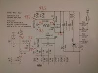
fiddle with P1 to get approx half of Ub at Q1 drain
remind me - why you go to almost double voltage , comparing to original F2 ?
re-check voltage across R16 - it must be in range of 600-700mV
if isn't (and it was in your previous posting) replace Q3 and/or Q2
I've skipped the parallel resistors and so my load resistance will be much higher than with them in, I got very low output and after reading closer on Zen i figured that increasing voltage in proportion to current should increase power output at 8 ohm and higher.
Voltage over R16 is 590mV, I was just too quick last measuring and didn't wait for rail voltage to settle enough.
Ub is rail voltage right?
Twiddling with P1 changes Q1 drain voltage from 2.94 - 9.24 V so I cannot get it to 24.
replace R5 with 1K ( or just solder another 2K2 across existing 2K2 ) and then try again
write what you got
your SS is "opened" too much , behaving as too small resistor , to have appropriate voltage sag across it
Just swapped R5 with 1K, I still can't get Q1 Drain to half the rail voltage but it can get much higher than before. It can get in between 3,14 - 17,88 V. Should I set it to some value and then post node voltages to ground or should something more be swapped?
Thanks again,
Olle
I think R4 needs to be higher from my experience if bias is too low, but I have not tweaked mine in some time.
What value would you recommend replacing R4 with?
And if I swap R4 should I keep R5 as 1k or should I revert R5 first?
If I understand correctly the "correct" R4 value would be that which enables me to while spinning P1 get Q1 drain to cover up to half rail voltage, 24V in my case and some more as marginal?
What possible max of Q1 drain voltage after P1 spin do you recommend I aim for while testing R4 values?
What possible max of Q1 drain voltage after P1 spin do you recommend I aim for while testing R4 values?

Tested to revert R5 and swap R4 with 3,3 k and got ~ 10 V max at Q1 Drain.
Does there need to be some ratio in between R4 and R5 to ensure stability or am I free to test different R there until I get the magical 24V at Q1 Drain?
Thinking of increasing R4 until I get there, current plan is to test a 6,8 k or 10 k. Or swapping R5 to 1 k again and then increasing R4.
Does there need to be some ratio in between R4 and R5 to ensure stability or am I free to test different R there until I get the magical 24V at Q1 Drain?
Thinking of increasing R4 until I get there, current plan is to test a 6,8 k or 10 k. Or swapping R5 to 1 k again and then increasing R4.
Last edited:
With R5 set to 1k and R4 to 7,3 k I got Q1 drain max up to 29V.
So I tested to minimize for distortion on a dummy load again and then started pushing until it starts clipping. Got unclipped signal 5,5 W @ 8 ohm and 3 W @ 16 ohm, nice. Distortion is not as nice above 1 W though =)
Q1 Drain voltage after distortion tweak is currently 19,9V.
Thanks for the help, if you happen to know any more tweaks that improves performance no one will be more happy than me =)
Last edited:

- Home
- Amplifiers
- Pass Labs
- DIY F2 clone