L=8/6.28*10000hz I get .000127 which I think is
0.127mH
0.127mH
Thanks Jacco,
I am afraid to do first order, somethin with no cap - I would like to put cap in there. Well other xover is second order.
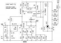
One thing I've thought about is the power supply of the F2J, I already have a fairly good CRCRC supply so I wonder how much of the top part I can skip and how much I need to keep.
If I understand correctly I can skip atleast R23-R26 but can I skip more of the circuit? And is LED1, C6 and R22 needed for the circuit?
If I understand correctly I can skip atleast R23-R26 but can I skip more of the circuit? And is LED1, C6 and R22 needed for the circuit?
Another thing I've wondered is about the load impedance.
I'm planning on biamping 2x 8 ohm mids. I will remove the parallel resistor since I want a current source with as high output impedance as possible to reduce driver distortion.
The question though is if I would get better performance from connecting the mids in series or if I should parallel them. If I've understood correctly the best would be to connect in series but I'm no expert so I might as well ask here =)
One thing I've thought about is the power supply of the F2J, I already have a fairly good CRCRC supply so I wonder how much of the top part I can skip and how much I need to keep.
If I understand correctly I can skip atleast R23-R26 but can I skip more of the circuit? And is LED1, C6 and R22 needed for the circuit?
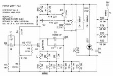
I think LED1 and R22 are not needed, C5 (i did not see C6) reminds me of the 10uF at the output of the BA PSUs, I suppose not bad against oscillation.
No, I do not think you can skip more, the remaining parts are all important for the CCS with the upper IRF.
But the anti plopp might be either the combination of C4 and R21.
Or are R23-26 also important for this function?
It seems I read the schematic wrong at first, I thought I saw that C6 was included with R22 and the Led, which I also foun strange
")
But aren't R23-26 just like the series resistors in a normal CRC psu, like the one recommended for the F5? So I who already have a CRCRC can skip them since they won't add any real value.
...they won't add any real value.
Hmm, just a little inductive coefficient. Easy (and cheap!) enough to checkout how this precious performs with or without it...
Another thing I've thought about:
Is it okay if C4 and C6 are say 20 cm away from the rest of the circuit?
I would prefer the amp to be as flat as possible for ease of mounting, so I thought I'd move the big capacitors to a kinda buffer-board ~ 20 cm away.
And secondly, is there a reason C4 and C6 are exact those values? Would it be a problem to exchange them both with a single one with a much higher value?
And thirdly, is the 24V V+ supply in the schematic expected to be raw output from an 18V transformer or is it expected to be filtered with say a CRC?
Another thing I've thought about:
Is it okay if C4 and C6 are say 20 cm away from the rest of the circuit?
I would prefer the amp to be as flat as possible for ease of mounting, so I thought I'd move the big capacitors to a kinda buffer-board ~ 20 cm away.
And secondly, is there a reason C4 and C6 are exact those values? Would it be a problem to exchange them both with a single one with a much higher value?
And thirdly, is the 24V V+ supply in the schematic expected to be raw output from an 18V transformer or is it expected to be filtered with say a CRC?
I do not know if you can put the caps so far away, but why not simply trying it? Connected with a thicker cable ....
As you can see in the two schemes I posted the C6 was added later, maybe to make less hum or the plopp still lower, I would say you can combine....May be for lower ESR!
Yes of course after the rectifier you need CRC!
Last edited:
I wanted to check some of the numbers on my p2p F2 Lite.
I built it with the following schematic:
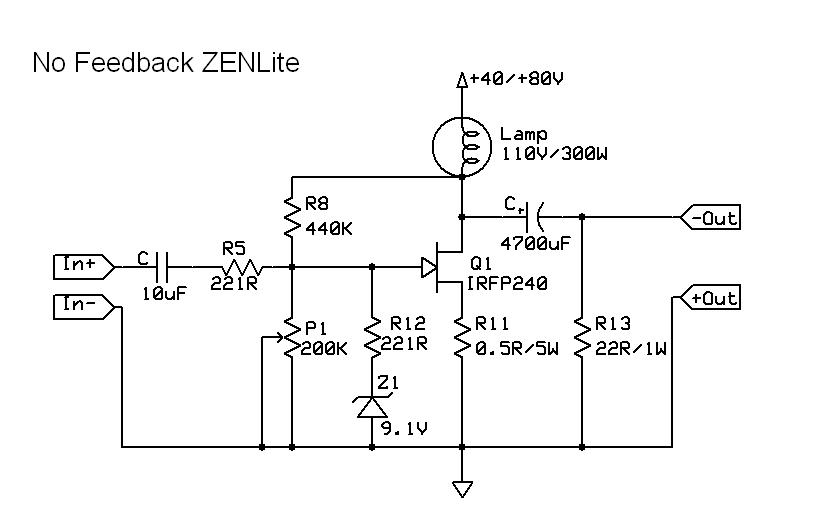
I used the following values:
R5= 221
R8=440K
R12= 221
9.1V Zener
R11= 0.25 5W
R13= 15R (2x30R 2w)
P1 I started with 175K then added resistors to reach 87K and then again to get 58K
Caps
In 1uf MKP
out 2200 uf
200W lamp
IRFP240
I have CRC w 0.33 and Zen V4 Reg
After filtering I have 54.5V after first cap
53.9V after R in CRC
49.1V after Reg
Where Im confused is after the 200W bulb I only measure 5V
@ 175K =5V
@ 87K =5.1V
@ 58K=5.5V
I was thinking it should be somewhere between 12-15V here. Is there something off or did I measure it wrong? Or do I need to lower P1 value more?
Also, how do you measure or calculate the resistance of the bulbs?
200W bulb @ 49V
Thanks for any input.
Steve
I built it with the following schematic:
I used the following values:
R5= 221
R8=440K
R12= 221
9.1V Zener
R11= 0.25 5W
R13= 15R (2x30R 2w)
P1 I started with 175K then added resistors to reach 87K and then again to get 58K
Caps
In 1uf MKP
out 2200 uf
200W lamp
IRFP240
I have CRC w 0.33 and Zen V4 Reg
After filtering I have 54.5V after first cap
53.9V after R in CRC
49.1V after Reg
Where Im confused is after the 200W bulb I only measure 5V
@ 175K =5V
@ 87K =5.1V
@ 58K=5.5V
I was thinking it should be somewhere between 12-15V here. Is there something off or did I measure it wrong? Or do I need to lower P1 value more?
Also, how do you measure or calculate the resistance of the bulbs?
200W bulb @ 49V
Thanks for any input.
Steve
I not at it now, but I think it was 0.2V, does that sound right?
It sounds very nice hooked up to some minimus 77 4inch fullrange, and more than loud enough off my soundcard. It does seem to not hold it together on more complex music at louder volumes. Thats why I wanted to check it out in more detail.
source R is 0.25R 5 W dale.
It sounds very nice hooked up to some minimus 77 4inch fullrange, and more than loud enough off my soundcard. It does seem to not hold it together on more complex music at louder volumes. Thats why I wanted to check it out in more detail.
source R is 0.25R 5 W dale.
I not at it now, but I think it was 0.2V, does that sound right?
It sounds very nice hooked up to some minimus 77 4inch fullrange, and more than loud enough off my soundcard. It does seem to not hold it together on more complex music at louder volumes. Thats why I wanted to check it out in more detail.
source R is 0.25R 5 W dale.
Two lamps paralleled could give you 1,6A. Now there seem to flow only 0,8A.
It seems you do not use the bulb values from the picture with 110V/300W?
Your bulb has a high resistance and you loose too much on the lamp ......I suppose.
Why do you not use the biasing network from the original F2 ?

I will build a standard F2. I have pcb from Peter Daniel. The lights are just for fun. I'm not sure it's the bulbs: I put 2x 200W bulbs and still only 5.4V after bulbs ( with 58k). No change basically.
Source resistor is 0.2 V with one bulb, 0.1 V with two bulbs, I'm going to check everything again. Thanks for looking and trying to help, I know you guys will get me in the right direction, I will break out the scope and see what it's doing also!
Steve
Source resistor is 0.2 V with one bulb, 0.1 V with two bulbs, I'm going to check everything again. Thanks for looking and trying to help, I know you guys will get me in the right direction, I will break out the scope and see what it's doing also!
Steve
The "nominal" resistance of a 200W/110V bulb should be 60.5 Ohms
P=VxV/R so R=VxV/P=60.5 Ohm
But That is when you feed it 110V and the filament is hot.
Cold it will be lower than that... since your PSU is only 49V, the resistance should be lower
If you measure 0.2V accross R11=0.25W, it means the current is 0.8 A, the bulb resistance should be V=RxI R=V/I=(49-5)/0.8=55 Ohm
If you want 1.6 Amperes and the drain of the MOSFET at the midpoint of your power supply (25V), you are looking for a bulb which will give you a resistance of ~16 Ohm
(V=RxI <=> R=V/I= 25/1.6 = 15.625Ohm)
Paralleling 3 x 200W bulbs should bring you to the right ballpark. But I would first try with 2 as generg suggested because as you add more bulbs, the filaments will get colder (as a result of the voltage decreasing) and the resistance of each will decrease.
Well I found a 300W bulb in the junk box. So 1x200W and 1x300W increased the volatge after bulbs to 7V or so, bulbs win! I can see the voltage being proper when I get 2x300W bulbs....
It is funny when I built these modules years ago I did the 2x300W bulbs and all seemed well, I did not know that different bulbs would do so much to circuit. Thats why I was asking the formula to calculate the light bulbs resistance value.
I have some large 50R 20W power resistors that I might hang on the bulbs to keep the smaller 200W bulbs in play ( I want a small Zen Light amp, lol). Its all about tinkering, and trying to actually understand something I build not just fill in the holes on a pcb. I did toast a mosfet tonight when I dropped a alligator clip tinkering the circuit, that kinda pissed me off, anyways...
thanks for the help guys!
Source resistor is 0.2 V with one bulb, 0.1 V with two bulbs,
Steve
Are you sure ???
It doesn't quite make sense, as the current should be higher...
You put the bulbs in parallel right ?
I've wondered about one thing, the output caps to the speakers are if I understand correctly just to remove DC and work in the same way as series capacitors in crossovers?
Because I'm planning 16 ohm speakers from 400 hz and upwards and if I understand correctly then I don't need as large capacitors as 15m uf but rather can get away with 1 m uf taking up less space =)
I posted these following measurements of my Monacor SPH-170, which should be a 90 db eff driver in the NCore thread but some here might also find them interesting: The measurement values aren't measured SPL, I estimate the 60 in the graphs is more around 75-80.
First up the NCore, which has very low distortion but is a voltage source amp:
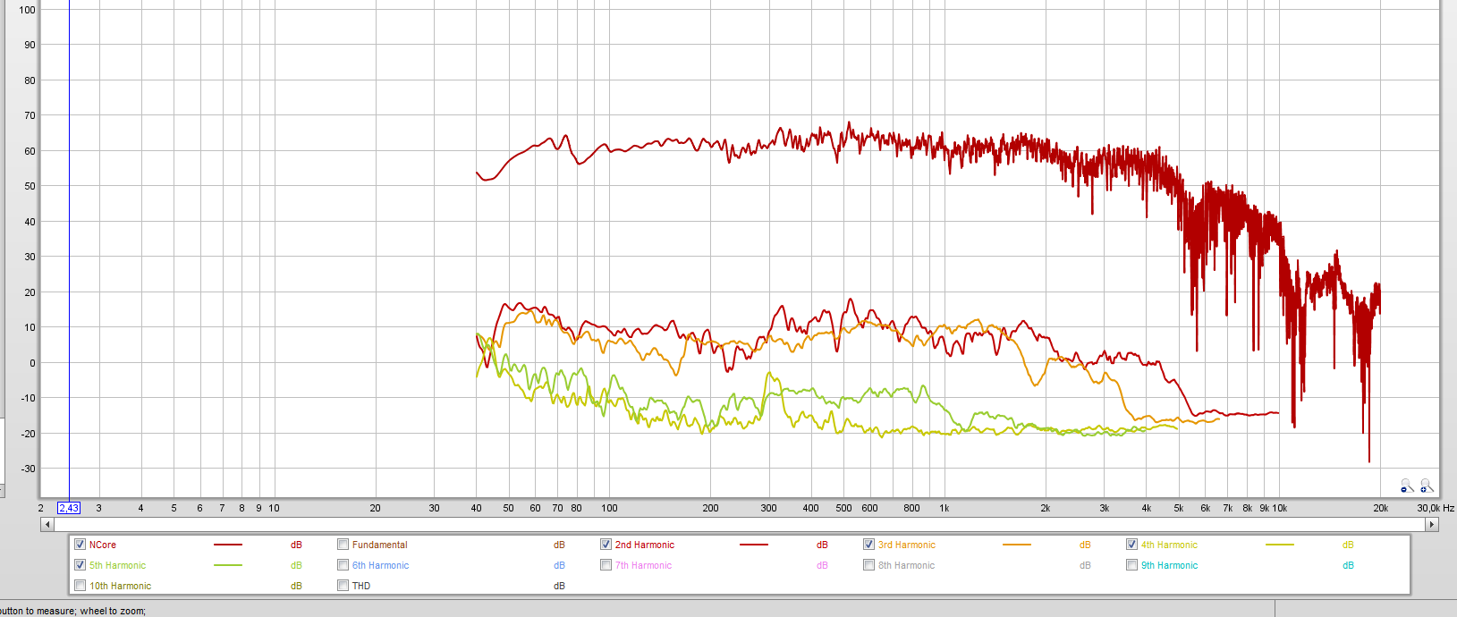
And now the F2J, without the parallel resistors ofc
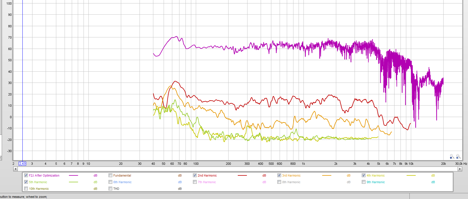
Makes one wonder why current source amplifiers aren't more common, since the difference isn't exactly small. Guess which amp I'm planning to build 4 of to take care of my mids and highs?
Because I'm planning 16 ohm speakers from 400 hz and upwards and if I understand correctly then I don't need as large capacitors as 15m uf but rather can get away with 1 m uf taking up less space =)
I posted these following measurements of my Monacor SPH-170, which should be a 90 db eff driver in the NCore thread but some here might also find them interesting: The measurement values aren't measured SPL, I estimate the 60 in the graphs is more around 75-80.
First up the NCore, which has very low distortion but is a voltage source amp:
And now the F2J, without the parallel resistors ofc
Makes one wonder why current source amplifiers aren't more common, since the difference isn't exactly small. Guess which amp I'm planning to build 4 of to take care of my mids and highs?
Last edited:
- Home
- Amplifiers
- Pass Labs
- DIY F2 clone