Hi Jens,
Sounds great!
I can't remember if we touched on this or not, but when using a single ended source, what is the best way to run the signal into the balanced inputs? I just ordered some XLRs so I could make adapters, they should be here tomorrow.
My good XLR cables are right angle, so I can't do a loop-back test yet.
-Chris
@kannan_s = Your problem with the noise is that the Noise Floor on REW is more fat than the AudioTester?
This is cause from Smoothness Filtering on AudioTester, REW hasn't any smoothness.
The term of smoothness in REW is Average.
Hi Lemon
nyt's plot shows the noise floor below all the distortion components and noise is much lower than what I see in my loop back test? under same conditions Audio tester THD + noise figure is much lower than REW?
kannan
@anatech
The Sound System Interconnect from Rane is always a good starting point
http://www.rane.com/pdf/ranenotes/Sound_System_Interconnection.pdf.
If you use configuration no. 13 you will probably have to use a wire between the equipment under test and the analyzer to avoid large common mode signals.
The Sound System Interconnect from Rane is always a good starting point
http://www.rane.com/pdf/ranenotes/Sound_System_Interconnection.pdf.
If you use configuration no. 13 you will probably have to use a wire between the equipment under test and the analyzer to avoid large common mode signals.
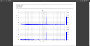
I managed to build and test a small add-on board today. The circuit works as intended and solves the problem with high levels of distortion. See attached measurement report.
Looks good Jens - great work
")
Also modding only one channel while the other is 'the old reference' is a very nice and clear way to show the mod works.
Last edited:

Demian hasn't complained about it, but I don't know if he tested at high levels. As long as you work at line levels there is no issue.
Back from post #1316:
Looking back at previous correspondence with Demian, he did actually comment on it at one point. For some reason, I didn't get to the bottom of it at the time.
@Microfast
Could you try attaching the picture using the forum "Manage Attachments" function?
Thanks Jens, the manner that I do use in other forum here doesn't work ...
Attachments
I think it is your amplitude scaling, look at how others have set their vertical range. It looks good to me.
Hi Lemon
nyt's plot shows the noise floor below all the distortion components and noise is much lower than what I see in my loop back test? under same conditions Audio tester THD + noise figure is much lower than REW?
kannan
I can see significant difference at noise floor, perhaps there is some difference at the level of harmonics, but if there was different test setup is normal.
i am not familiar with these spectrum analyser sw, I test with ARTA usually. All of these sw need a carefully calibration before use them.
In ARTA, I follow the calibration procedure with 1Vrms at input, this level will be the 0dBV at the vertical range.
Please, read the documentation files of these and how these are calibrated and then repeat the loop-back test with the vertical range from 0...-160dB, the level of gen at 0dB(FS), 1,000,05Hz and follow the rest as nyt done.
The best with THD+N will be at -5dBFS almost.
The best with THD will be at -15dBFS almost.
There is a small difference btw yours and nyt tests,
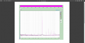
Good catch, I enabled "Lock frequency to FFT" option in the Generator and obtained same level of noise performance as nyt
Both output and input are configured at 0dB, and REW calibrated under this setting before loopback measurements.
Attachments
If you go to -12 to -15dBFS, you will have the best THD.
If you set the generator signal at -1dB, you will have the best of the best.
Can you try with IMD 19+20KHz (1:1)?
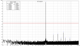
IMD 19+20kHz measurement with ARTA attached.
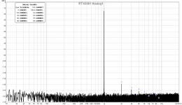
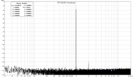
Also attached the REW measurement at -15 and -18dBFS, my unit gives the lowest THD at the -18dBFS level.
Attachments
Last edited:
IMD 19+20kHz measurement with ARTA attached.
Also attached the REW measurement at -15 and -18dBFS, my unit gives the lowest THD at the -18dBFS level.
Perfect!
-18dBFS is your sweet spot for THD measurement.
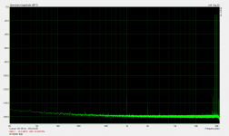
Please, take another capture of IMD 19+20 (1:1) with linear view, it must begin somewhere of 900Hz to 22KHz. The generator at -1dBFS, Kaizer (Wnd), Exp (Avg)
It will seem more clearly the range btw 10K-22K
Last edited:
- Home
- Design & Build
- Equipment & Tools
- DIY Audio Analyzer with AK5397/AK5394A and AK4490